


CubesAreShapes
New Member
- Joined
- Aug 27, 2022
- Messages
- 14
Hello everyone!
First, I'd just like to thank you for taking the time to read my thread. I have been doing a lot of research but thought it would be prudent to create a thread specifically for my system to get personalized advice. I feel extremely grateful that there are knowledgeable people on these forums willing to help others out.
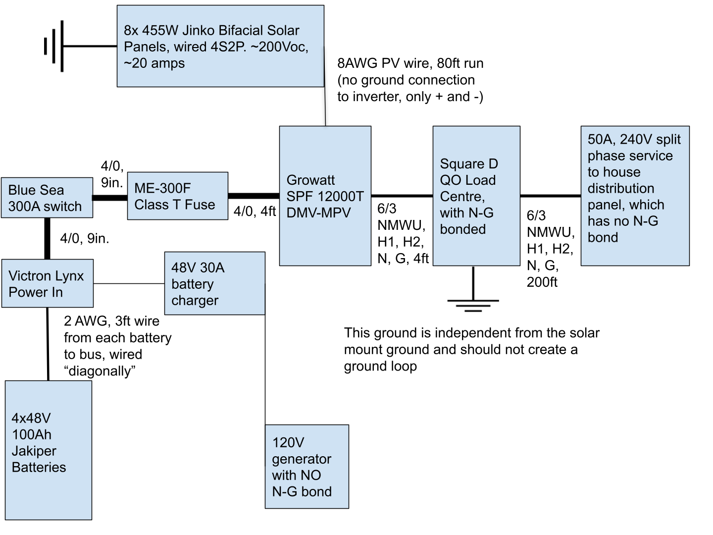
My system is for an off-grid tiny house in Ontario, Canada, about 500sq ft. The tiny house has a standard 50A outlet tied into a Square D QO breaker panel (with no N-G bond, I might add) that distributes power to the house. The house has 240V split-phase appliances (stove, heat pump, maybe dryer in the future).
Diagram of proposed setup:
Currently, I own these components:
- Growatt SPF 12000T DMV-MPV all-in-one inverter (http://www.ginverter.com/upload/file/contents/2021/07/6101469b85988.pdf though site currently seems down? Alternate: https://solarpowerstore.ca/products...0vac-split-phase-out-of-the-box-not-stackable)
- 4x48V 100Ah Jakiper Server rack batteries with open rack (https://jakiperbattery.com/product/server-rack-battery-jk48/)
- 8x455W Jinko Bifacial Solar Panels (https://www.jinkosolar.com/uploads/TR JKM445-465M-7RL3-TV-A1.1-EN.pdf)
- Victron Lynx Power In (its my bus bar - enclosed rack with built in bus bar is another option)
- Various wires (Using 2 AWG from batteries to Victron Lynx Power In and 4/0 from bus bar to inverter, all from WindyNation)
- Blue Sea 300A m-series battery switch (Also have Blue Sea HD-series switch which has two outputs, and would use this if I switched to the EG4 inverter since eventually likely have two and can use the same switch for both. I'll return the unused switch to Amazon) (https://www.amazon.ca/gp/product/B00445KFZ2/ and HD: https://www.amazon.ca/gp/product/B000MMDLB6/)
- Square D by Schneider Electric QO612L100DF QO 100-Amp 6-Space 12-Circuit - the output from the inverter will go here and have a 50A circuit going to the tiny, a small 15A circuit for an outlet in the solar shed (has all the components in it, built 80ft away from the solar panels), and maybe one day a circuit to charge an electric car. (https://www.amazon.ca/gp/product/B00CONNDSC/)
- Magnum Energy ME-300F 300 Amp Fuse Block Assembly and Class T (https://www.amazon.ca/gp/product/B00OM9AB1I/)
- Grounding rod (https://www.amazon.ca/gp/product/B09BLZ2M58/)
- 3 to 1 PV Combiner Box, almost exactly like this one:
- Misc: purchased flir one gen 3 for my phone to see wire/connection temperatures after installation (https://www.amazon.ca/gp/product/B0728C7KNC/), Klein Tools CL800 (https://www.amazon.ca/gp/product/B019CY4FB4/), and Klein Tools RT210 GFCI Receptacle Tester (https://www.amazon.ca/gp/product/B01AKX8L0M/)
- 48V AC LiFePo4 Battery Charger 30A (https://solarpowerstore.ca/products/48v-ac-lifepo4-battery-charger)
Things I still need to figure out:
- Do I need to add more fuses? I plan to use a combiner box which has fuses for the solar panels (15A iirc), and have a large 300A fuse between the inverter and the bus bar. Do I need to put a 100A-125A fuse between each battery connection and the bus bar? If so, maybe I should get the Victron distributor which has slots for the fuses?
- Is there value in wiring the fuse before the switch? It would save more wire that way?
- Is it better/different at all to wire the ground to the Growatt case directly, or to the distribution panel where I bonded N-G?
- I can return the Growatt 12k and am strongly considering doing this in favour of the EG4 6000W split phase unit (https://signaturesolar.com/eg4-6k-off-grid-inverter-6000ex-48hv/) - maybe starting with just one for now, and adding more later if I need the capacity. The manual seems clearer, and being able to call Signature Solar is nice. I think this might simplify the grounding problems I was reading about in the huge growatt 12k passthrough thread?
- Gauge of PV wire. It's probably going to be carrying ~250-500V (250 if I stick with Growatt, 500 if I switch to EG4) and ~30 amps about 80ft. Thinking of going with 8AWG here.
- How to ground this. I'll have no AC input (no grid-tie, and instead of buying a 240V generator, I will use my existing small 120V generator to power a 20-30A 48V battery charger wired into the Victron Lynx Power In). My current plan is to ground the solar panel frames to a 4ft copper grounding rod, and not connect this ground to anything else. Beside the solar shed, I'll have another 4ft ground rod that the inverter case is wired into, and this will be carried through to the Square D QO panel where I have the N-G bond (the only one AFAIK). I have read about grounding the negative bus bar, but I do NOT intend to do this. AFAICT that is a European thing, which makes sense because the Lynx has a ground bolt on the negative bus bar and they're a European company.
- I have not picked out a shunt
- Should I return the Victron Lynx and get an enclosed battery rack with built-in bus bar?
I'm going to come back and refine this post as I learn more and make decisions, I'm also working on a diagram that shows all of this together and will add it to this post when it's ready.
Thank you so much for any input you can provide! I have no one to talk to about this in real-life so all of your input and help is super valuable and appreciated. I feel like I owe so much to these forums already so it is tough to ask for help without being able to offer anything in return...so I will, at the very least, try to do my best to document this build for someone else in the future to reference.
First, I'd just like to thank you for taking the time to read my thread. I have been doing a lot of research but thought it would be prudent to create a thread specifically for my system to get personalized advice. I feel extremely grateful that there are knowledgeable people on these forums willing to help others out.
My system is for an off-grid tiny house in Ontario, Canada, about 500sq ft. The tiny house has a standard 50A outlet tied into a Square D QO breaker panel (with no N-G bond, I might add) that distributes power to the house. The house has 240V split-phase appliances (stove, heat pump, maybe dryer in the future).
Diagram of proposed setup:
Currently, I own these components:
- Growatt SPF 12000T DMV-MPV all-in-one inverter (http://www.ginverter.com/upload/file/contents/2021/07/6101469b85988.pdf though site currently seems down? Alternate: https://solarpowerstore.ca/products...0vac-split-phase-out-of-the-box-not-stackable)
- 4x48V 100Ah Jakiper Server rack batteries with open rack (https://jakiperbattery.com/product/server-rack-battery-jk48/)
- 8x455W Jinko Bifacial Solar Panels (https://www.jinkosolar.com/uploads/TR JKM445-465M-7RL3-TV-A1.1-EN.pdf)
- Victron Lynx Power In (its my bus bar - enclosed rack with built in bus bar is another option)
- Various wires (Using 2 AWG from batteries to Victron Lynx Power In and 4/0 from bus bar to inverter, all from WindyNation)
- Blue Sea 300A m-series battery switch (Also have Blue Sea HD-series switch which has two outputs, and would use this if I switched to the EG4 inverter since eventually likely have two and can use the same switch for both. I'll return the unused switch to Amazon) (https://www.amazon.ca/gp/product/B00445KFZ2/ and HD: https://www.amazon.ca/gp/product/B000MMDLB6/)
- Square D by Schneider Electric QO612L100DF QO 100-Amp 6-Space 12-Circuit - the output from the inverter will go here and have a 50A circuit going to the tiny, a small 15A circuit for an outlet in the solar shed (has all the components in it, built 80ft away from the solar panels), and maybe one day a circuit to charge an electric car. (https://www.amazon.ca/gp/product/B00CONNDSC/)
- Magnum Energy ME-300F 300 Amp Fuse Block Assembly and Class T (https://www.amazon.ca/gp/product/B00OM9AB1I/)
- Grounding rod (https://www.amazon.ca/gp/product/B09BLZ2M58/)
- 3 to 1 PV Combiner Box, almost exactly like this one:
- 48V AC LiFePo4 Battery Charger 30A (https://solarpowerstore.ca/products/48v-ac-lifepo4-battery-charger)
Things I still need to figure out:
- Do I need to add more fuses? I plan to use a combiner box which has fuses for the solar panels (15A iirc), and have a large 300A fuse between the inverter and the bus bar. Do I need to put a 100A-125A fuse between each battery connection and the bus bar? If so, maybe I should get the Victron distributor which has slots for the fuses?
- Is there value in wiring the fuse before the switch? It would save more wire that way?
- Is it better/different at all to wire the ground to the Growatt case directly, or to the distribution panel where I bonded N-G?
- I can return the Growatt 12k and am strongly considering doing this in favour of the EG4 6000W split phase unit (https://signaturesolar.com/eg4-6k-off-grid-inverter-6000ex-48hv/) - maybe starting with just one for now, and adding more later if I need the capacity. The manual seems clearer, and being able to call Signature Solar is nice. I think this might simplify the grounding problems I was reading about in the huge growatt 12k passthrough thread?
- Gauge of PV wire. It's probably going to be carrying ~250-500V (250 if I stick with Growatt, 500 if I switch to EG4) and ~30 amps about 80ft. Thinking of going with 8AWG here.
- How to ground this. I'll have no AC input (no grid-tie, and instead of buying a 240V generator, I will use my existing small 120V generator to power a 20-30A 48V battery charger wired into the Victron Lynx Power In). My current plan is to ground the solar panel frames to a 4ft copper grounding rod, and not connect this ground to anything else. Beside the solar shed, I'll have another 4ft ground rod that the inverter case is wired into, and this will be carried through to the Square D QO panel where I have the N-G bond (the only one AFAIK). I have read about grounding the negative bus bar, but I do NOT intend to do this. AFAICT that is a European thing, which makes sense because the Lynx has a ground bolt on the negative bus bar and they're a European company.
- I have not picked out a shunt
- Should I return the Victron Lynx and get an enclosed battery rack with built-in bus bar?
I'm going to come back and refine this post as I learn more and make decisions, I'm also working on a diagram that shows all of this together and will add it to this post when it's ready.
Thank you so much for any input you can provide! I have no one to talk to about this in real-life so all of your input and help is super valuable and appreciated. I feel like I owe so much to these forums already so it is tough to ask for help without being able to offer anything in return...so I will, at the very least, try to do my best to document this build for someone else in the future to reference.
Last edited:


