ron_jeremy
New Member
This off-grid solar setup was built many years before I moved to this home. The setup consists of:
- 24V Trace Engineering SW4024 inverter (120V only).
- 24V 23kW FLA battery bank (12 x 2V 960AH cells).
- 8 x 75W Siemens panels (hilarious, I know) in what looks like to me as two strings of four panels run in parallel.
- Xantrex 150V/60A SCC.
- Trace Engineering DC disconnect (the throw handle has “250” written on it).
- Trace Engineering AC disconnect (25A on L1 only)
- Yamaha EF4500iSE generator (battery charging).
Here's what the two strings look like:

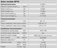
Existing panel specs:

Lower string connects to upper string (combiner box?):

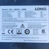
I have purchased the following from Santan Solar:
- Victron 150V/60A SCC.
- PV cable.
- Two x 20A MC4 inline fuses.
- Six x 350W panels.

The Plan:
- Disconnect the parallel connection (in combiner box thingy) between the two strings and remove old panels.
- Install three new panels on lower mount and run cable to the existing 150V/60A SCC plus install 20A fuse on positive cable close to panels.
- Install three new panels on upper mount and run cable to the new 150V/60A SCC plus install 20A fuse on positive cables close to panels.
- Configure each SCC for new panels (if required).
- One array to face SW for morning sun and the other W-ish for afternoon sun.
I can’t quite get behind the battery bank to confirm this, but it looks like the PV cable enters the garage (right beside the battery bank where I can’t see anything), goes up into the existing SCC, and then out to the battery bank main terminals.
Questions:
- What equipment needs to be disconnected or turned off before I do anything?
- Is there a proper order for disconnecting equipment (for example: SCC 1st, combiner box 2nd, arrays 3rd, etc.)?
- Can I still use the same DC disconnect for both strings or do I need to add a 2nd one?
- Am I missing anything or is anything ‘out of whack’ spec-wise?
- I see videos where a "shunt" is used at the positive terminal. What is this for?
- In the near future, I plan to add one more string of panels and a 3rd SCC (250V/70A). Any issues with this? Basically, can I add as many SCC’s and panels as I want or is there a limiting factor I’m not thinking of?
- 24V Trace Engineering SW4024 inverter (120V only).
- 24V 23kW FLA battery bank (12 x 2V 960AH cells).
- 8 x 75W Siemens panels (hilarious, I know) in what looks like to me as two strings of four panels run in parallel.
- Xantrex 150V/60A SCC.
- Trace Engineering DC disconnect (the throw handle has “250” written on it).
- Trace Engineering AC disconnect (25A on L1 only)
- Yamaha EF4500iSE generator (battery charging).
Here's what the two strings look like:

Existing panel specs:

Lower string connects to upper string (combiner box?):

I have purchased the following from Santan Solar:
- Victron 150V/60A SCC.
- PV cable.
- Two x 20A MC4 inline fuses.
- Six x 350W panels.

The Plan:
- Disconnect the parallel connection (in combiner box thingy) between the two strings and remove old panels.
- Install three new panels on lower mount and run cable to the existing 150V/60A SCC plus install 20A fuse on positive cable close to panels.
- Install three new panels on upper mount and run cable to the new 150V/60A SCC plus install 20A fuse on positive cables close to panels.
- Configure each SCC for new panels (if required).
- One array to face SW for morning sun and the other W-ish for afternoon sun.
I can’t quite get behind the battery bank to confirm this, but it looks like the PV cable enters the garage (right beside the battery bank where I can’t see anything), goes up into the existing SCC, and then out to the battery bank main terminals.
Questions:
- What equipment needs to be disconnected or turned off before I do anything?
- Is there a proper order for disconnecting equipment (for example: SCC 1st, combiner box 2nd, arrays 3rd, etc.)?
- Can I still use the same DC disconnect for both strings or do I need to add a 2nd one?
- Am I missing anything or is anything ‘out of whack’ spec-wise?
- I see videos where a "shunt" is used at the positive terminal. What is this for?
- In the near future, I plan to add one more string of panels and a 3rd SCC (250V/70A). Any issues with this? Basically, can I add as many SCC’s and panels as I want or is there a limiting factor I’m not thinking of?
Last edited:


