diy solar

diy solar

Two To One Terminal Block for BMS and Balancer

ChrisG

Solar Addict
Joined
Sep 23, 2019
Messages
1,557
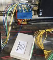
Looking at using terminal blocks pictured below to rebuild two packs, make it a cleaner build. Goal is to have on lead for each battery for both BMS and Balancer to a terminal block then split bms and balancer on other side of terminal block.

Is this a good idea? Want to make sure all the voltages are able to be read correctly by each device and function as expected. I would assume so but want to know if anyone else has gone down this path. IMG_3604.jpeg
 
do not use the same wires for BMS sense and a separate balancer. The balancer activity will notably influence the cell voltage readings.

When a BMS has active balance as part of its feature set, it can compensate for it. When it's a separate balancer, the BMS has no idea what's happening.

Set of wires to BMS
Set of wires to balancer
 
Last edited:
do not use the same wires for BMS sense and a separate balancer. The balancer activity will notably influence the cell voltage readings.

When a BMS has active balance as part of its feature set, it can compensate for it. When it's a separate balancer, the BMS has no idea what's happening.

Set of wires to BMS
Set of wires to balancer
You think you could get around that by only charging to 3.46v per cell, and enabling the Balancer at 3.45v? This would make sure the charging current is low or nothing when the balancer comes on, and if the BMS sees a large deviation because of the active balancer, it won't be enough to cause problems.

How much deviation will the balancer influence on that sense lead anyways? 30-40mV?
 
I turned off balancing on my BMS when I installed my balancer. The BMS still served many functions including a very accurate SOC estimate.
 
do not use the same wires for BMS sense and a separate balancer. The balancer activity will notably influence the cell voltage readings.

When a BMS has active balance as part of its feature set, it can compensate for it. When it's a separate balancer, the BMS has no idea what's happening.

Set of wires to BMS
Set of wires to balancer
True statement. I used 18Ga wire from the BMS to the Cell terminals and combined the balancer wire in the Ferrule that is inserted in the BMS screw terminal. The wire isn't very long, I thought 18Ga was sufficient for a 2A balancer. The cell voltages definitely move when the balancer is active, not the just the 1 cell either but the 2 on each side. Its not enough to cause problems under normal circumstances but if a cell is close to a limit, the deviation could push it over causing the BMS to disconnect.

Per Lt.Dan, the deviation is more like 10 to 15mV and enabling balancing at 3.4V and above is recommended.
 
the deviation could push it over causing the BMS to disconnect.
And if cell voltages are that high anyways, turning off the charging circuit is not the end of the world. The battery is already fully charged.

I do think the lead to the cells have to be appropriately sized. 18ga minimum.
 
These are 48v packs. I use an overkill BMS and heltech 5a balancer for each pack. I turned off the passive balancer on BMS and have a relay to stat balancing at 3.45v and absorption stops at 3.52v. Would use larger wire due to 5a, like 16Ga. Stopping charging wouldn’t be the end of the world.

Still bad idea? Lol. Glad I posted here.
 
While not using yet any Terminal Block between BMS/Battery, I was considering single middleman units. But also though about another point of connection failure and decided against it.
 
These are 48v packs. I use an overkill BMS and heltech 5a balancer for each pack. I turned off the passive balancer on BMS and have a relay to stat balancing at 3.45v and absorption stops at 3.52v. Would use larger wire due to 5a, like 16Ga. Stopping charging wouldn’t be the end of the world.

Still bad idea? Lol. Glad I posted here.
Andy of Off Grid Garage got way with it a couple of times. But I don’t know what his BMS thought about it.
Larger shared wires would probably mitigate the issue
 
Curiosity had me check; Heltec active balancer 5 amp 16AWG leads, Neey active balancer 4 amp 20AWG, JK BMS 2 amp 22AWG, Daly BMS 50ma? 22AWG

Edit the Heltec is actually 18AWG- poor printing and old eyes.
 
Last edited:
I use this 2 to 1 connector on one of my 3 packs and don't see any difference in operation. Heavy wire from the busbars and deactivate the BMS balancer.
 
I use a din rail terminal block. Fused heavier wiring from the block to the busbar minimises BMS sense wire distortion.
 

Attachments

  • IMG_0176.jpeg
    IMG_0176.jpeg
    617.3 KB · Views: 20
Back
Top