diy solar

diy solar

Understanding Battery Aging

Thanks!

Re: fuses, I'm planning to use a terminal fuse as the main fuse so I can connect it right to the battery bank positive, and branch from there. Maybe a good way to do it would be to have the main terminal fuse be rated at 250A, and then have a 175A fuse after that goes to the inverter, and another branch with a 60A fuse that goes to the charge controller. So maybe like a double terminal fuse holder on top of a single terminal fuse directly on the battery terminal. Does that make sense?

Should I move my further questions to a new thread??
 
Last edited:
Thanks!

Re: fuses, I'm planning to use a terminal fuse as the main fuse so I can connect it right to the battery bank positive, and branch from there. Maybe a good way to do it would be to have the main terminal fuse be rated at 250A, and then have a 175A fuse after that goes to the inverter, and another branch with a 60A fuse that goes to the charge controller. So maybe like a double terminal fuse holder on top of a single terminal fuse directly on the battery terminal. Does that make sense?

Should I move my further questions to a new thread??

I wouldn’t stack fuses like that. Get some custom length cables from BatteryCablesUSA.com. Good prices and high quality cables.

What size cables will you use for the main battery cables, inverter and charge controller? You want to fuse for the wire rated capacity not the device.

Also, consider bus bars. Tidier, can save $$ on expensive copper cables and much better than wiring everything directly to the battery. Terminal fuse on the battery, cables to bus bars. Then everything else has their own fuse and cables, wired to the bus bars. The 250A brass ones are cheaper and are fine if you keep your loads under about 175A.

What inverter and charge controller are you using?
 
This is a ghetto fabulous system on the cheap, so stacking the fuses is to keep the cost down, so thanks for the tips in that arena! The terminal fuse holder is a cheap-o from Amazon, but I might just make one with busbar material.

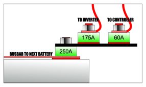
Here's how the battery fuses would look:

Battery Fuse Plan.jpg
Doesn't seem too crazy, but it's still a work in progress.
 
Also researching cheap-o busbar material. Getting some conflicting info between this chart and this calculator regarding the relationship between cross-sectional area (CSA) and ampacity.

Example: Chart shows this re: a 3/4" x 1/8" (19.05mm x 3.175mm) copper busbar:
  • Cross Section Area(cm) 19.4 (?)
  • ampacity at 215A.
The CSA should be 60.5mm², and according to the calculator, the ampacity would then only be 72.58A.

Which should I rely on?
 
I'm assuming the calculator is correct, although I don't understand how the chart could be so off... And for the record, I calculated the ampacity of copper pipe using data from this chart to make the following chart:

Copper Pipe Busbar Ampacity Chart.jpg

I used 1.2 Amp/mm² for the calculations. Is that correct or am I missing something?
 
I'm assuming the calculator is correct, although I don't understand how the chart could be so off... And for the record, I calculated the ampacity of copper pipe using data from this chart to make the following chart:

View attachment 157032

I used 1.2 Amp/mm² for the calculations. Is that correct or am I missing something?
Yes, temp rise.

Bare copper busbar doesn't have insulation like a wire. The calculator is basing ampacity based upon insulated wire cross section to a busbar.

Use the first chart, it agrees with other information out there.
 
But what about the chart having wonky CSA numbers? 19.05mm x 3.175mm should be 60.5mm² not 19.4cm. Or is that a unit other than centimeters?
 
This is a ghetto fabulous system on the cheap, so stacking the fuses is to keep the cost down, so thanks for the tips in that arena! The terminal fuse holder is a cheap-o from Amazon, but I might just make one with busbar material.

Here's how the battery fuses would look:

View attachment 157003
Doesn't seem too crazy, but it's still a work in progress.
Have you actually looked at an MRBF type fuse holder? It isn't just a bus bar ... the stud on the fuse holder is insulated from the bar the fuse sits on. These are protection devices that will hopefully never be used. It would be foolish to try to rig up something when the real deal fuse holders are so cheap. buy these and sleep well at night https://shop.pkys.com/Blue-Sea-5191-Single-Terminal-Fuse-Block-30-300-Amp_p_7755.html

For fuses I want to know they are manufactured and tested to perform. Don't cheap out on fuses, especially when you want to experiment with mixing different capacity batteries.
 
Also, I planned to shrink tube the busbars. Will that throw off the ampacity, or is it too thin compared to wire insulation?
 
Have you actually looked at an MRBF type fuse holder? It isn't just a bus bar ... the stud on the fuse holder is insulated from the bar the fuse sits on. These are protection devices that will hopefully never be used. It would be foolish to try to rig up something when the real deal fuse holders are so cheap. buy these and sleep well at night https://shop.pkys.com/Blue-Sea-5191-Single-Terminal-Fuse-Block-30-300-Amp_p_7755.html

For fuses I want to know they are manufactured and tested to perform. Don't cheap out on fuses, especially when you want to experiment with mixing different capacity batteries.
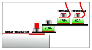
Excellent advice, thank you! The diagram I drew does include an MBRF holder as the upper part. Maybe I just need two instead of going directly on the battery terminal on the main fuse...
 
OK so to answer some of my own questions, cm in this case isn't centimeters, it's a unit known as "Circular Mils, Thousands," as I found on another sheet.
 

diy solar

diy solar
Back
Top