diy solar

diy solar

Unregulated 24 V to 12 V DC converter

SunnySoCal

New Member
Joined
Jan 8, 2022
Messages
49
Here's what I've got:
Victron 100/50 SCC

Xantrex Freedom X 2000 W 12 volt (recent upgrade from 600 Xantrex PSW)

Hodge podge of panels all with very close Vmpp as configured (some 12 V in 2S and some 24 V) so array voltage ~36 V (Vmpp). Note that I bought panels with the Vmpp within a +/- 0.2 V range (as configured).

Recently added another 300 AH LiFePo4 (now have two of these) in parallel.

I only recently added the extra battery so that I could meet my design goal (again, also a new goal, after buying the 2000W inverter) of running my 7 cu ft freezer and a minifridge indefinitely if needed. Both have 11 A Locked Rotar Amp (LRA) compressors and why I bought the Xantrex (surge capabilities). The extra battery was to have 2-3 days of clouds/rain.

My dilemma is I think I've snookered myself as at 12 V I'm running 50/600 = 0.08 C charge rate. With my current ~36 V array the Victron limits at 50 Amps for hours around noon even this time of year. Will obviously be much worse outside of winter solstice

So, in hindsight, I should have bought a 24 Volt inverter. The Victron will run 24 V and thus I could double my power into batteries if I put them in series but now have 24 V battery which is not compatible with the inverter, obviously.

The other thing I liked about the Xantrex is it's adjustable LV disconnect.

What I'm thinking of doing is building a DC - DC (24V to 12V) high power converter. Yes, one can buy them but then I'd need to utilize another LV disconnect as they all seem to regulate the 12 V...something one would normally want...but this would defeat the inverter LV cutoff function.

I'm a retired EE and have breadboarded many circuits over my lifetime (and started at age 12 with a 3 tube shortwave radio kit). I'd like to build at least 100 Amp (at the 12 V), want it to track the nominal 24 voltage to maintain the inverter's LV cutoff function. I'm not as concerned about efficiency as the cost of panels seem to be nearly irrelevant wrt total system costs. I've got about 1000 W of panels but also have some shade issues, especially this time of year (high fence w/neighbor, and 5 palm trees clumped together to my south-west).

As another question, I've read lots of posts wrt best array voltage for MPPT. Seems like 2 - 2.5 times battery voltage is considered the sweet spot. If I stay at 12 V would running at ~ 54 V (reconfigure my series/parallel panel configuration) buy me anything?
 
I would have thought that a retired EE would have researched this more thoroughly before going out and randomly buying stuff. You've painted yourself into a corner, but it's not the end of the world. The mistakes are correctable, but you are going to have to spend some more money.

First question, can those two batteries be wired in series to create a 24V battery bank? I think the optimal solution is for you to forget 12V and graduate up to 24V. That would entail getting rid of the 12V inverter, and replacing it with a 24V model. The good news about that though is that once you go up to at least 24V, the choices of quality inverters, with extra added features, greatly improves. You might be able to sell the 12V inverter on Ebay, maybe as "new in the box" or "new, open box", and get back most of the money.

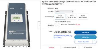
The second choice would be to stick with 12V but replace the Victron 100/50 with a more capable controller. The budget brand, Epever has this...
1670174440256.png

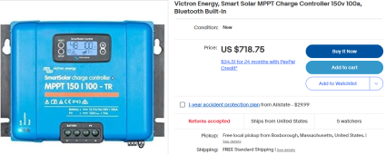
If you want to stick with Victron, they also make a controller in that size, though you'll paid dearly for it...
1670174529735.png
Again, you might be able to sell the smaller controller on Ebay, and recoupe some of your money.

The last thing to comment about is this statement....
Hodge podge of panels all with very close Vmpp as configured (some 12 V in 2S and some 24 V) so array voltage ~36 V (Vmpp). Note that I bought panels with the Vmpp within a +/- 0.2 V range
You only mention the Vmp, you mention nothing about amps. A important thing to remember about parallel strings of panels is in series, panels of differing voltages may be wired in series, but they need to be close to the same amperage (5%). Strings of panels of differing amperages may be wired in parallel, but their voltages in series need to be the same (5%). Please post the specs of each panel, Vmp, Voc, Imp, Isc. Then we can help you wire them in the most effective manner.

One final option is just buying a second (or third) Victron 100/50 SCC controller, and wiring them in parallel to charge the batteries. Can the Victron controllers communicate with each other? If so, then link them together. If not, make sure all the charging parameters are exactly the same.
 
Last edited:
Before I respond to criticism, I will put out my call for help if anyone has experience designing/building the following:

DC to DC converter with about 50 amps @ nominal 24 V DC input and 100 amps output @ nominal 12 V and with the output voltage following proportionally the input voltage.

If not, feel free to not respond...

General guidelines or web links would be great. Topology, components, etc. I've got the power handling wiring/heatsinking/construction techniques figured out. I'm open to using a 2:1 transformer after a DC-AC conversion (yes, probably old school but I'm expecting a reasonably "dumb" circuit) and then rectifying the output. My gut says power MOSFETs are part of the solution. I'd expect somewhat simpler than DC - DC converters on market because I want a proportional output to keep my LV cutoff within the inverter operational. Also, thought this might be useful device for others to upgrade at minimal cost. Sharing ideas on a forum, no?

As to the above response, of course I've thought of all of the workarounds you've indicated. My intention is to worst case keep all of my current equipment and if reasonably straightforward build the DC-DC converter described above else I would not have posted. If not, I will just live with it...including the possibility of nominal 54 V operating array as the Victron SCC is rated to 100 Voc.

My first system (circa 2000, so not my first rodeo) was a 50 W panel, two 6V Sam's Club deep cycle batteries (still have for core value!) and a 10 amp PWM SCC (which had a 12V separate load o/p) and a MSW inverter. My second was purchasing more panels over the years (and a 60 A PWM SCC) and a big Trojan battery, 600W Xantrex PSW. I've always kept Vmpp close when buying 100 W panels (and when I bought my 2 200W 24V panels they were almost exactly twice the Vmpp of the 100 W panels...else I wouldn't have purchased). My understanding is that the currents only need to match up in series panels which they do (all of my 100 panels in series are identical make/model). I have 6 100w panels in series (3 x 2) and two 200w, all in parallel. From memory I knew they were all about 5 amps...I just went outside and it turns out the 100 V are 5.23 A and the 200 V are 5.28 A (well within manufacturing tolerances).

Finally, I was always taught to respect my elders. Nothing random about my purchases...just requirements change...but yes, as mentioned above had I known that this was going to be a goal I would have known to go 24V on inverter. Perhaps I should have stated that this goal is for backup only (grid down). If that were to happen all of the current power usage would be sidelined in favor of just my fridge/freezer operations.
You're in luck.

Cllena DC 24V Step Down to 12V 100A 1200W DC/DC Voltage Converter Regulator Waterproof Buck Transformer Power Supply https://a.co/d/2blbnME
 
Hey thank you, Checkthissout...I had looked on Amazon but didn't find this one. I will keep this one in mind, but it does put out a constant output voltage (and the 1 star reviews for the high power unit not too appealing). For sure I don't think I could build for this low a cost. If need be, I could utilize a work-around for a LV cutoff. Have all the "hunks and pieces" around but ideally I wanted to maintain the LV cutoff within the inverter. Still looking for diy circuit ideas.
 
Hey thank you, Checkthissout...I had looked on Amazon but didn't find this one. I will keep this one in mind, but it does put out a constant output voltage (and the 1 star reviews for the high power unit not too appealing). For sure I don't think I could build for this low a cost. If need be, I could utilize a work-around for a LV cutoff. Have all the "hunks and pieces" around but ideally I wanted to maintain the LV cutoff within the inverter. Still looking for diy circuit ideas.

I don't know how your inverter is switched but if it's something like a simple rocker switch just get an adjustable voltage relay to turn it on and off based on battery voltage.

You could also paralell cheaper units for more current.

Can't be of any help on the circuits.

I would suggest just buying another charge controller. With multiple operating voltages, it will never obsolesce should you choose to go to a higher voltage in the future.

The higher voltage your array in relation to battery voltage, the lower the charging efficiency due to higher switching frequency and current rates in the controller. It turns more electricity into heat.
 
Last edited:
Well, my original issue was "clipping" of the charge current @50A (which is what my Victron 100/50 does) and both respondents suggested buying another charge controller... adding a Victron in parallel, or a MPPT charge controller with higher current rating. That got me to thinking about paralleling my Victron with my Schneider (aka Xantrex) C60 PWM that served me well for several years. I googled the crap out of mixing PWM and MPPT and didn't find anything but positive takes on this. When I get around to it, I will remount and move about 300 W of panels to this charge controller. No cost solutions are the best! BTW, as all I believe know, the 50 A isn't really battery current if one has loads running...it's the sum of the loads plus what goes into the battery...
 
Update...just before the holidays I got my old 60A PWM up in parallel. Happy that I did that, and everything seems to be ok. I have a clamp current meter and read about 35% of the Victron MPPT current going into the battery w/the PWM. I know there's other ways to calculate input amperage (kWh, etc) but I will just use about "1/3 more" than my Victron (bluetooth ap) tells me I'm producing. I have a kill-o-watt out there on the AC side (for kWh consumed) which I've been resetting daily until I get a good feel for my production/consumption with my setup. All good...
 
Back
Top