diy solar

diy solar

Valence XP Super Thread

I’ve had my laptop connected about a month now nonstop and two of my batteries won’t balance. They both have one cell bank that won’t go above 3.3v. I’m guessing this is why the batteries were retired. Has anyone else experienced this?

Yes, I acquired two U27-12XPs off eBay. Same thing, one module had only 69 charge cycles and goes to 14.9 volts and the other to only about 13.6volts. On the one that only goes to 13.6volts it has about 560 charge cycles and one of the packs in the module never seems to get over 3.3volts. I have these wired in Series, so they are really unbalanced during the absorption charge cycle, one at 14.5 and other at 13.6. When the charger goes into float they both settle down to about .2volts of each other.
 
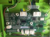
I did some testing with the high-voltage valence branded u-BMS. I'm happy to report it's working. I have it controlling for contactors although I'm really only utilizing two of them. I flashed the BMS for 2 batteries in series. The hv u-BMS needs 100 volts dc minimum because it's the high-voltage version and I only had 24 volts there so I used a power supply and it works. Each battery was at 100% state of charge and then I hooked a 12-volt charger to one of the batteries removed the side cover on the battery and monitored the voltage across the resistor responsible for balancing the battery. Both started at 13.4 volts they had been resting for over a month. When the battery hooked to the charger reached 13.49v suddenly battery voltage appeared across the resistor and the large rows of resistors on the bottom left begin to get warm.

The next test I'd like to do is to raise the batteries voltages together and see if the resistor will activate at some point over 14.6 even though they're balanced. I doubt they'll activate but I know at some point the BMS will disconnect the battery Bank to stop from going over voltage.
 
Yes, I acquired two U27-12XPs off eBay. Same thing, one module had only 69 charge cycles and goes to 14.9 volts and the other to only about 13.6volts. On the one that only goes to 13.6volts it has about 560 charge cycles and one of the packs in the module never seems to get over 3.3volts. I have these wired in Series, so they are really unbalanced during the absorption charge cycle, one at 14.5 and other at 13.6. When the charger goes into float they both settle down to about .2volts of each other.

Now that I have had my batteries running a few days the weak cells pack in my module seems to be closer to the others. It took a few cycles of absorption charging to pull it up. But, it still seems to lag the others consistently. Fortunately at this point in time, I am not doing any real deep discharging overnight (3-5%) so it doesn't vary too much. As I increase the depth of discharging on the pack (I am connecting a 24/1200 Victron Inverter to run a refrigerator) I will see how it performs long term.
 
!!! VALENCE. u-BMS SUCCESS !!!

Last week I finally got the OEM u-BMS fully functional and tested, I proved to myself it's working and doing its job. Now that I finally figured it out I realize it's so much easier than other DIY's like building your own with tons of wires. It's literally just flash plug and play!
 
[QUOTE = "Travis, message: 78831, membre: 7065"]
Pour que votre configuration simple en parallèle réussisse à équilibrer les quatre blocs de cellules à l'intérieur de chaque batterie, vous n'avez besoin que d'un ordinateur portable. Comme je l'ai déjà dit, ils doivent communiquer avec quelque chose ou ils n'arrivent pas tout simplement pas à l'équilibre. Je suppose que la communication des systèmes victron n'est pas suffisante pour y parvenir. En fait, il n'y a absolument aucun système à l'exception du système de valence et des systèmes de rechange spécialement conçus à cet effet qui permet l'équilibrage.

Je suppose que votre onduleur un point de destinataire de tension d'arrêt personnalisable qui est bon car il ne déchargera pas trop les batteries, mais comme il s'agit d'un VR dont vous parlez, vous allez probablement avoir de simples frais de 12 volts tirant la puissance de la batterie pour que vous ayez besoin d'un relais qui déconnectera les batteries lorsqu'elles seront mortes ou vous les ruinerez. Ne pensez pas que vous pouvez faire attention parce que personne ne fait assez attention. Vous devez absolument éliminer un système automatisé pour déconnecter les batteries lorsque la tension devient trop faible.

Les moniteurs de batterie bon marché que j'ai postés au début fonctionneront bien pour cela. Obtenez simplement la tension et l'ampérage adaptés à vos besoins.

Maintenant, si vous voulez être encore plus confus
puisque vous ne traitez pas avec autant de batteries, vous pouvez facilement retirer complètement la carte d'équilibrage de valence et remplacer par une unité de rechange qui couvrent l'équilibrage et la déconnexion de sécurité basse et haute tension dans une seule unité. Ils coûtent environ 100 $ et vous aurez besoin de 1 pour chaque batterie. Je n'aime pas que ce soit seulement 100 ampères parce que vous êtes un onduleur capable de dessiner deux cents ampères. Si vous avez acheté ce type, vous devriez probablement en empiler trois sur la première batterie, puis vous pouvez déplacer vers les autres batteries si vous en avez d'autres plus tard.

Le fonctionnement du système de valence n'est vraiment pas meilleur que les autres marques tant que vous n'en avez pas beaucoup en série.
[/CITATION]
 
Bonjour, pouvez-vous nous donner un lien pour acheter cette carte d'équilibrage? Je vous remercie
 
Bonjour, pouvez-vous nous donner un lien pour acheter cette carte d'équilibrage? Je vous remercie
there are a lot of different brands shapes and sizes. A lot of different options. It might be better to get an external contactor and let the 12-volt power run through it instead of the BMS board. Simply use the BMS high amperage connectors to control the contactor. Maybe the aftermarket BMS will fit inside the xp battery. I've never tried it because I don't like this idea. It's a lot easier to utilize the original valence BMS now that I understand how to do so.

il existe de nombreuses formes et tailles de marques différentes. Beaucoup d'options différentes. Il pourrait être préférable d'obtenir un contacteur externe et de laisser le courant de 12 volts le traverser au lieu de la carte BMS. Utilisez simplement les connecteurs BMS à ampérage élevé pour contrôler le contacteur. Peut-être que le BMS du marché secondaire s'adaptera à l'intérieur de la batterie xp. Je ne l'ai jamais essayé car je n'aime pas cette idée. Il est beaucoup plus facile d'utiliser le BMS de valence d'origine maintenant que je comprends comment le faire.


!!! VALENCE. u-BMS SUCCESS !!!

Last week I finally got the OEM u-BMS fully functional and tested, I proved to myself it's working and doing its job. Now that I finally figured it out I realize it's so much easier than other DIY's like building your own with tons of wires. It's literally just flash plug and play!
Travis,
I'm a lurker here following this thread. I have 10 U27-XP's Rev 1 (black with M12 connectors) batteries. I have Ver 12.12 of the software and have 4 modules in an RV and 4 in a sailboat. The RV batteries have dipped into the low voltage cutoff area at one time (and turned the led indicators red) and this had me searching for a solution not to destroy my batteries. Here I am. When I finally got the software to work on my laptop, I connected to my RV batteries and one at a time got the red led to change to green! The sailboat battery bank of 4 have behaved nicely: not much use yet.
Anyways: You got a U-BMS HV to work with a low voltage battery bank? Or - you have a LV version? Please elaborate. As stated in this thread, there are a lot of U-BMS HV units for sale but not the LV version.
 
!!! VALENCE. u-BMS SUCCESS !!!

Last week I finally got the OEM u-BMS fully functional and tested, I proved to myself it's working and doing its job. Now that I finally figured it out I realize it's so much easier than other DIY's like building your own with tons of wires. It's literally just flash plug and play!
hello Travis ,I bought a couple of used U27-12XP battery off ebay, at the time I thought they had a complete BMS built in, I later learned otherwise. I want to put these two batteries in parallel in my winnebago view . Just bought 4x 100 watt panel to permanent mount on roof, and have a 100 watt suitcase panel I will add to the system so it can be moved with the sun.Seems there are three options for a BMS for the Valence batteries. Thunderstruckmotors sells a Master BMS for the batteries for $250 but it does not have a temp control. The other would be Muller Industry BMS for the valences at $600 and they have been out of stock for months...so not really an opinion. However the Renogy DC-DC controller might be a solution. Has over voltage protection, overheat protection/battery temp. My question is, will this controller protect the Valence batteries or am I missing something? Any suggestions about using these batteries would be helpful.
 
Ok I have found a lot of information on your post. Started reading and will try communication with the batteries via computer when I get the hardware ready and the software downloaded and running. Your post have been very useful, sure I will need help as I get thought this project, like to have this solar system on my RV in the next month or so. Chas
 
Yes, I acquired two U27-12XPs off eBay. Same thing, one module had only 69 charge cycles and goes to 14.9 volts and the other to only about 13.6volts. On the one that only goes to 13.6volts it has about 560 charge cycles and one of the packs in the module never seems to get over 3.3volts. I have these wired in Series, so they are really unbalanced during the absorption charge cycle, one at 14.5 and other at 13.6. When the charger goes into float they both settle down to about .2volts of each other.
Travis responded to my post back on page 4 about this issue, and despite my trying I couldn't get them to balance. I owe Travis a huge Kudos on this topic because he took my two problem batteries and he did exactly what he recommended in his reply and viola! got those two problem cells back up. It's actually really easy, just takes some time. adambant, take your problem battery out and put it on a direct charger until it behaves, and like Travis said, if you get impatient you can put voltage directly to the problem cell to bring it up faster. If you want I can post a picture of the battery's interior showing where the voltage goes. For the money that we've spent on these batteries it's definitely worth buying a $50 DC variable voltage generator to tune these things up.
 
One more shameless plug for Travis... I ordered one of those imitation U-BMS from China and it finally arrived months later, and didn't work. Travis hooked me up with a high voltage version of the U-BMS being powered by a simple $20 step-up transformer taking 12v up to 60v, and it's successfully running my 24v bank of U27-12XPs. Many, many thanks to all of your work, trial and error, and experiments on this. This is a really easy work around but it took a lot of work on Travis' behalf to put it all together. Thanks, man!
 
Try a charger like this so you can precisely control volts and amps.

Each cell Negative (-) uses the adjacent cell's positive (+). In the photo below, black wire/arrow is cell 1 (-), blue wire/arrow is cell 1 (+) AND cell 2 (-).
Yellow wire/arrow is cell 3 (+) AND cell 4 (-). Brown wire/arrow is cell 4 (+).

EXAMPLE: If you want to bring up cell #4, put your power supply positive (+) to the brown wire and your power supply negative (-) to the yellow wire. Keep the battery connected to the valence software to monitor the cell voltages while you are charging.

Let's say your problem cell #4 is 3.3v and all your others are 3.5v - - - > set your power supply connected to cell #4 to 3.5v, maybe 1/4 amp, and monitor from there. Once the cells all come together the battery SOC shown in the valence software will jump to 100%. Note- it may take hours and hours for the low cell to come up to reach the others.

val.jpg
 
Last edited:
Extremely helpful, thanks!
To be clear, are you removing the molex connector and pinning the charger into the female end? And the monitoring still works in that condition?
Cheers!
 
Extremely helpful, thanks!
To be clear, are you removing the molex connector and pinning the charger into the female end? And the monitoring still works in that condition?
Cheers!
No. Leave it connected. Attach a small wire hook from your charger output to where the colored wire in the photograph enters the connector. If the hook is small it will hang right there and make contact.
 
Ah, gotcha...Makes it easier still. I was beginning to wonder about genders of molex connectors...and decided for myself that male is the metal pin, not the plastic receptacle, which is technically 'female'...so even that can get confusing for us novices. Cheers!
 
hello Travis ,I bought a couple of used U27-12XP battery off ebay, at the time I thought they had a complete BMS built in, I later learned otherwise. I want to put these two batteries in parallel in my winnebago view . Just bought 4x 100 watt panel to permanent mount on roof, and have a 100 watt suitcase panel I will add to the system so it can be moved with the sun.Seems there are three options for a BMS for the Valence batteries. Thunderstruckmotors sells a Master BMS for the batteries for $250 but it does not have a temp control. The other would be Muller Industry BMS for the valences at $600 and they have been out of stock for months...so not really an opinion. However the Renogy DC-DC controller might be a solution. Has over voltage protection, overheat protection/battery temp. My question is, will this controller protect the Valence batteries or am I missing something? Any suggestions about using these batteries would be helpful.
No the renogy will not protect the batteries because it does not communicate with the internal board and it would not know the cell voltages. you'll end up quickly getting one cell over or under voltage and the renogy would have absolutely no idea it needed to disconnect the contactor. It also won't cause the internal board to balance the cells.
 
Hi all. I'm new to the thread here, but have been following for a few weeks. I've recently acquired a large number of these batteries and I'd like to get experience and opinion of others on charging.

I've done some testing using two chargers and always connecting the battery to the valence 1212 software.

First, I've tried 13.8v for battery one and 14.07v charging voltage for battery two with 24hr on each. These two batteries were done with a charger that has fixed voltage output. All cells stayed under 3.6v during charging and I noticed that the cell balencer was triggered after a cell spread of 50mv.

Second, I've used a smarter lithium charger, progressive dynamics lithium with a fixed voltage of 14.6v. Two batteries were done with this method producing similar results to the above but slightly faster. All cells stayed under 3.65v while charging, balencers kicked in at 50mv spread etc.

I have seen one commonality between all voltages and methods of charging. Each battery ends with one cell that is approx 30mv lower than the other three.

What is everyone else's take on charging? Are you seeing a similar situation?

I feel as though it's not just coincidence that all 4 batteries using difference charge methods have the same result. Also, since I'll be using the BMS and since the software itself doesn't seem to care until they're 50mv apart, should I really worry?

I can tell you've paid good attention to the details and you are correct to assume that there's no need to worry. I repeat there's no need to worry about the 50MV difference.

One thing to remember about the 14.6 volt charger is that if you are charging a battery thats severely out of balance it will overpower the bleed off resistor and drive one cell over-voltage so if You're balancing a battery for the first time you should pay close attention and probably use the lower voltage charger for that purpose. Any cell above 3.43 is pretty much full and the same state of charge as a cell that's at 3.8. if in doubt just look at the state of charge meter it will not jump to 100% until it is truly balanced.
 
Back
Top