diy solar

diy solar

Vanagon Solar/DCDC - Double check

vanwagon

New Member
Joined
Feb 2, 2023
Messages
13
Location
US
PXL_20230408_215355931.jpg
Slow progress, but I finally got a board sized up for the small space under the rear seat of a vanagon. I need to order up the bus bars, wires, and solar panels. When done this will have 200-300w of solar using Rich Solar 12v panels in parallel, 100ah of 12v LiFePO4 with room to expand to 200ah. No shore charging or invertor planned.

Does it look correct?
Is anything missing or something you would do differently?
Thanks in advance
 
I love Vanagons, especially the two I converted from the gutless 48hp diesel they came with to 90hp 1.8L gas golf engine (bombproof). They were all my surf and camping rigs.

Having had a few Vanagon Westfailures, wondering about the effect of heat from the nearby engine compartment on the charge controller etc. I don’t remember ever noticing heat in the area, but I wasn’t looking for it either. Plus I was most often in a coastal climate.
 
Good thought. I think the most warmth it gets under there is from the CDH tucked on the opposite side.

This was where the electronics are going. I plan to add some vent holes along the kick panel in front of it and separate the heater from the rest of things with partitions. I've seen others do the same without complaints but I'll keep an eye on the temps
PXL_20230408_230152791.jpg
 
Good thought. I think the most warmth it gets under there is from the CDH tucked on the opposite side.

This was where the electronics are going. I plan to add some vent holes along the kick panel in front of it and separate the heater from the rest of things with partitions. I've seen others do the same without complaints but I'll keep an eye on the temps
View attachment 143767
If any excessive heat 2 vents and a usb cpu type cooling fan w tstat should help with minimal parasitic draw.
 
Having had a few Vanagon Westfailures, wondering about the effect of heat from the nearby engine compartment on the charge controller etc. I don’t remember ever noticing heat in the area, but I wasn’t looking for it either. Plus I was most often in a coastal climate.

A good device will derate at the temperature increases. A bad device will just let the magic smoke out.
 
Thank you guys for the feedback on heat, but what I really need feedback on is the wiring and the diagram. Is there any omissions or incorrect findings?
 
Based on the Renogy diagram, your set up seem fine.

But you the breaker of the solar battery should be between the positive battery terminal and the busbar and close as possible to the terminal. Add a fuse near the terminal can do the job if you want to keep breaker near the Renogy.

Renogy dcdc 1000x1000-1__32973.jpg
 
The breakers you have shown have proved to be very unreliable, unless you can use Bussman/Bluesea or similar quality breakers , the use of fuses is a safer alternative. The fuses must be installed as close as practical to the starter and house battery positive terminals as shown.
Note the D+ control signal should not be needed.
DCC50.jpg
If your Renogy unit is the DCC50 it will pull over 60 amps from the alternator. Since the vehicle could use approaching 50 amps for use like heater, lights, wipers, AC, engine electrics, the standard alternator may be overloaded at low engine speed.

At the house battery you will need additional fuses to feed DC loads and a high current master fuse on the battery positive is recommended. For 12v lithium a MRBF with BlueSea holder is a neat solution.


Mike
 
At the house battery you will need additional fuses to feed DC loads and a high current master fuse on the battery positive is recommended. For 12v lithium a MRBF with BlueSea holder is a neat solution.
+1 for the fuse instead of breaker. Still breaker are convenient to disconnect something instantly.
If MRBF fuse terminal are not practical to put in place, find in line Midi or Mega fuse. Cheap and work great.
 
Thanks for the info and feedback.
Tape was my attempt to understand the connections and lengths before dealing with cables.

I am using the Renogy DCDC50 model with 100AH LiFePO4, so thanks for pointing out the concern of overwhelm the stock alternator. I will look at higher output alternators if I run into issues. It was my understanding that the DCDC50 can pull a maximum of 25amps from the alternator whenever solar input is sensed (the unit can only pull 50% of its max rating from each source, so as long as solar input is >0.0A, the alternator should be limited to 25 amps). Is this wrong to assume? I plan to size wires/fuses/breakers/etc. for a full uninhibited alternator load but hoped it would not routinely overload the stock alternator if only pulling 25 rather than 50 amps.

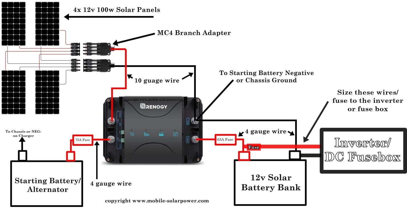
I'm a little disappointed with the feedback on breakers but will listen to the recommendations. I was following the schematic and parts listed here including location of the breakers:

From the recommendations posted:
- Add a MRBF or Mega fuse to the solar/house battery near the positive terminal.
- Add a MRBF or Mega fuse to the starter battery input near where it leaves the alternator.
- Place fuses as close as practical to the positive source (i.e., alternator, starter battery, solar battery).
- Keep the LEFT breaker on my diagram to allow manual disconnection of alternator charging
- Keep the RIGHT breaker on my diagram to allow manual disconnection of all charging sources (solar and alternator) from reaching the solar battery
- No need to connect the D+ connection on the Renogy DCDC/Solar unit. Noted.
- DC loads will all go through a blue sea fuse block with appropriately sized fuses and wires.

A few thoughts...
- Distance between the controller and the alternator is 3-4ft.
- Distance between the solar battery and the DCDC50 is 2ft.
- Distance between the bus bar and the fuse block for DC appliances is about 10ft.
- I do not plan to use an inverter.

Based on recommendations from the link above on mobile-solarpower.com I was going to use the following:
1) 4-gauge wire throughout the diagram except...
2) Each solar panel will get an inline MC4 fuse between the panel and branch connector, then will 10g wire will run to the DCDC50 unit.

Does this sound correct?
Anything I misunderstood from the recommendations above?
Any other recommendations?

Thanks again for all the help.
 
I'm not sure about your understanding on the alternator loads with solar present. The wording is not the clearest in that section of the manual. The installation manual does call for a 75 amp fuse on the alternator feed wire, so I tend to think it will pull more than 25 amps if the solar current is low.
 
I'm not sure about your understanding on the alternator loads with solar present. The wording is not the clearest in that section of the manual. The installation manual does call for a 75 amp fuse on the alternator feed wire, so I tend to think it will pull more than 25 amps if the solar current is low.

Based on posts in the forum, if there is any PV input then the alternator will never contribute more than 25 amps (on the output side of the device). Likewise, if there is any alternator input then the PV will never contribute more than 25 amp (on the output side of the device).
 
Based on posts in the forum, if there is any PV input then the alternator will never contribute more than 25 amps (on the output side of the device). Likewise, if there is any alternator input then the PV will never contribute more than 25 amp (on the output side of the device).
Interesting. That would push this controller further into the "Don't want!" category for me, then.
 
Interesting. That would push this controller further into the "Don't want!" category for me, then.

You have seen the light (bulb).
idea.gif
 
Yes. That is a big downfall of the device, however, with a small alternator and limited space in these vehicles, it does serve a purpose here. Fortunately at camp the alternator is not running so solar can run at full capacity. When driving the alternator wouldn't like pulling 50 amps anyway. But if I ever change it, I'll just throw in a switch to the solar and can remove that. I'm sure they'll improve it in the next iteration of this device or a competitor.

Any other suggestions?
 
Hi- From my Eurovan house system experience I can offer a bit of additional advice:
- I have slowly switched from cheap breakers to Busman version in my Eurovan after having one 80a cheapo throwing at 30 amps load. Breakers are so convenient for isolating and troubleshooting. I have also put fuses inline close to devices (Starter battery etc,) and left the breakers in for switching. I chose the fuses rated a bit higher than breakers so that hopefully the breaker will throw and not the fuse, but fuse is there for safety. Rereading, I see that this is your updated plan. Great.
- Run negative cable instead of relying on chassis ground.
- Upgrade alternator hot and battery ground to heavier ga or just add an additional 4 ga alongside factory cable to assure full capacity.
- Make sure to leave room for an inverter and charger in your installation. Both have turned out to be very useful for me. A 500VA PSW victron serves for laptop, coffee grinder wand mixer, dremel and tool charging.
Staying in friend's driveway, a discreet extension (repurposed vacuum cleaner cords!) runs to "shore" power keeps everything charging even when parked in the shade. I mainly depend on my folding panels but they're not always appropriate to situation. My additional roof panels are only 100w due to limited real estate on the roof (storage box and surfboard) and not usually adequate alone.
- I have been happy going with the Victron stuff when priced right but that DC to DC on the Renology is a selling point. I have no DC to DC just an upgraded alternator.
 
Back
Top