


dmkjr
Solar Enthusiast
Good evening. i have a MPPT 100/30 controller installed on my 5th wheel camper with a SmartShunt. It's the Solar Flex 400i package from Keystone.
I have added a Cerbo GX and I'm trying to utilize the system, replacing the stock inverter with an Ampvint 3000w inverter which allows me to run it in Battery Priority mode.
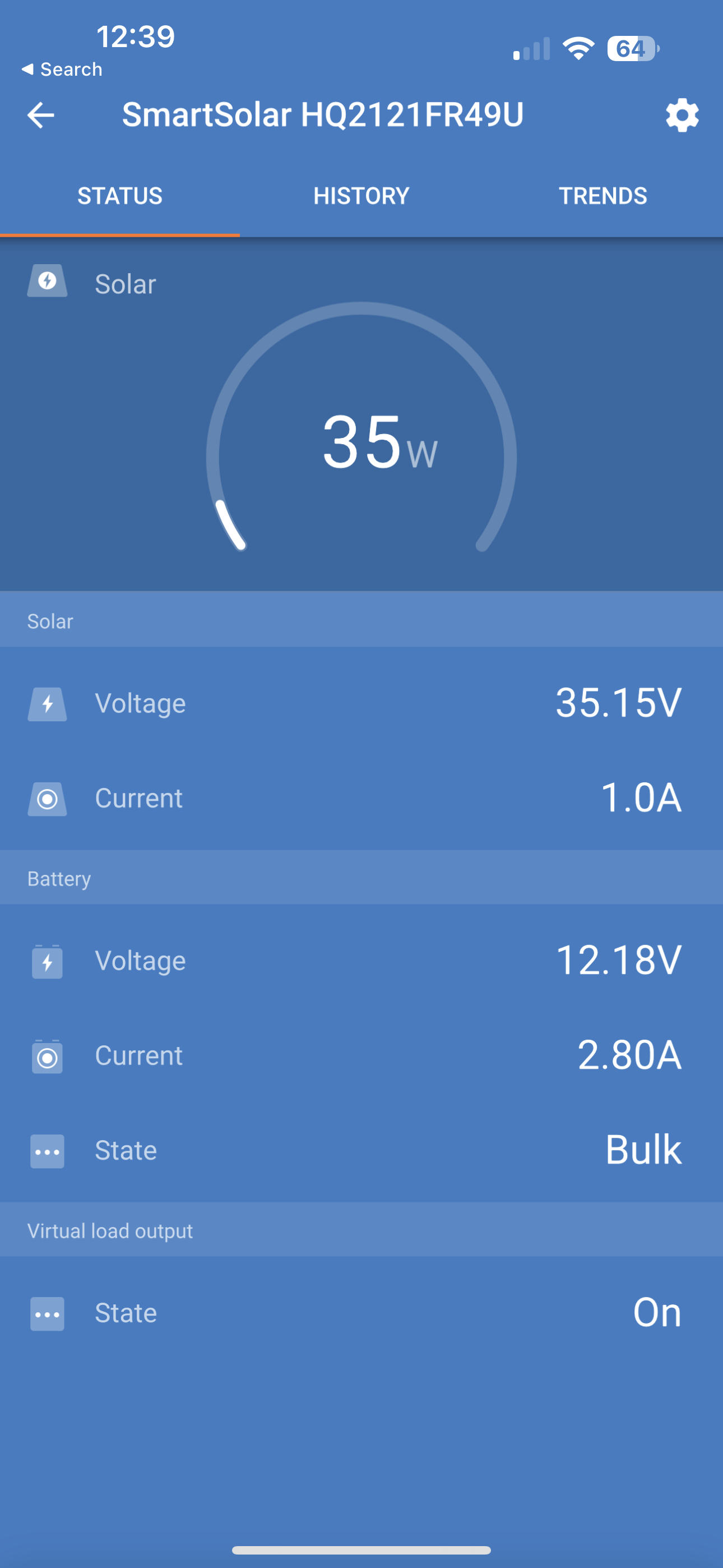
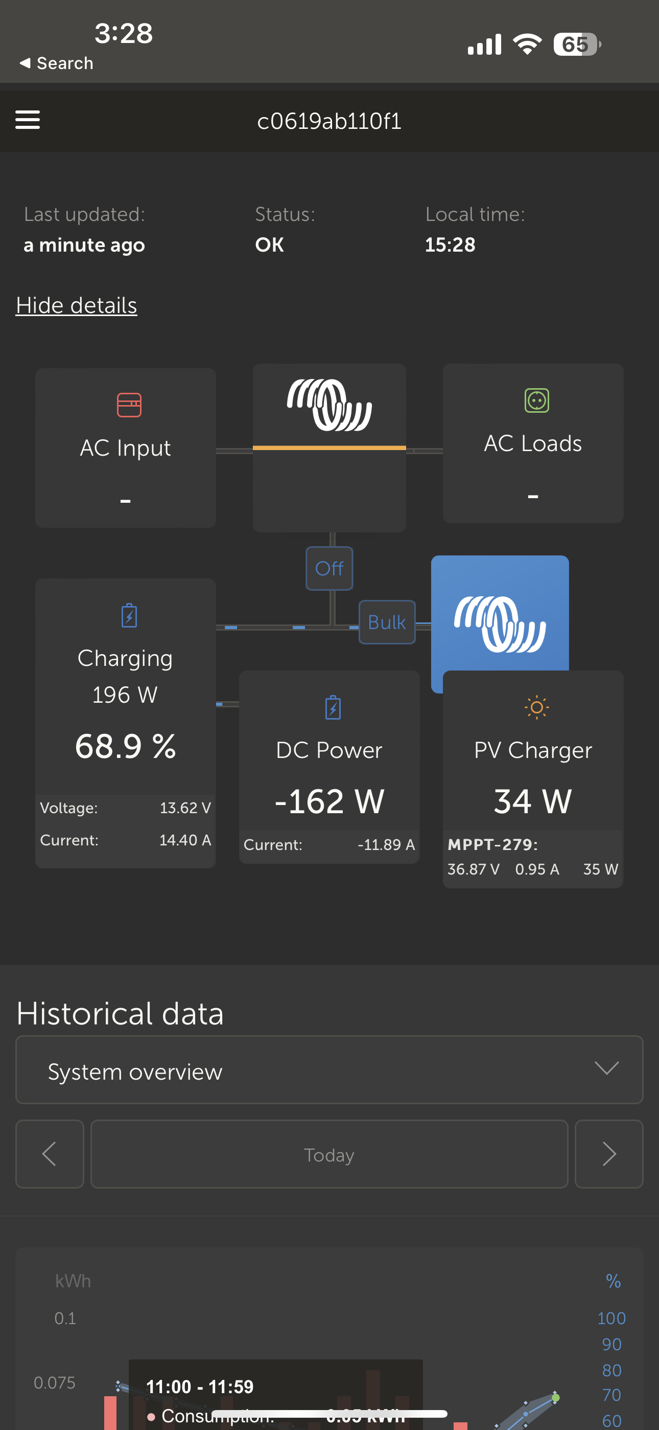
However, I think something may be wired wrong, or I don't completely understand the grounding requirements perhaps. The MPPT is not drawing much solar energy at all. I'm seeing 32-35 watts continuous from the controller, even when it was in Bulk mode. Voltage from is showing as 35.15v with 0.9-1a producing 35 watts. They are two 200 watt rated Future Solutions solar panels. It was sunny today, direct sunlight. Panels are wired in parallel.
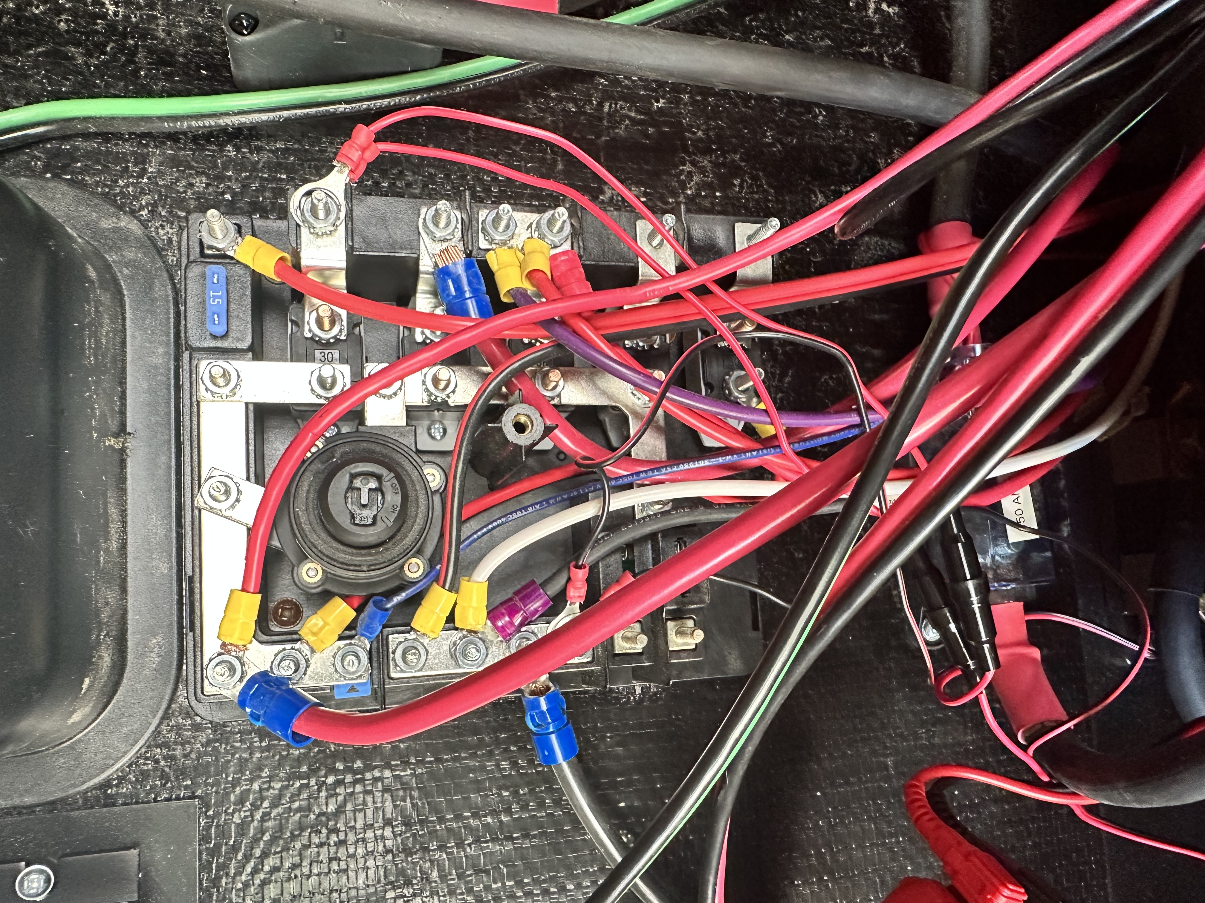
I'm going to post some pretty bad pictures. I haven't cleaned up the wiring yet.
Any ideas on what could be going on?
Thank you!
I have added a Cerbo GX and I'm trying to utilize the system, replacing the stock inverter with an Ampvint 3000w inverter which allows me to run it in Battery Priority mode.
However, I think something may be wired wrong, or I don't completely understand the grounding requirements perhaps. The MPPT is not drawing much solar energy at all. I'm seeing 32-35 watts continuous from the controller, even when it was in Bulk mode. Voltage from is showing as 35.15v with 0.9-1a producing 35 watts. They are two 200 watt rated Future Solutions solar panels. It was sunny today, direct sunlight. Panels are wired in parallel.
I'm going to post some pretty bad pictures. I haven't cleaned up the wiring yet.
Any ideas on what could be going on?
Thank you!
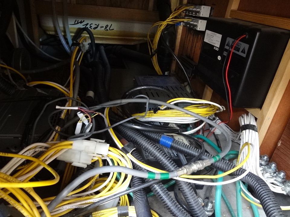
") Most of what looks rough there (the loose wiring) is from the recently installed Victron monitors. Gerbo GX and GlobalLink 520. They will get cleaned up and the black cover will go back on. In terms of the connections, that's Keystone for you.
Most of what looks rough there (the loose wiring) is from the recently installed Victron monitors. Gerbo GX and GlobalLink 520. They will get cleaned up and the black cover will go back on. In terms of the connections, that's Keystone for you.