SolarHawaii
New Member
- Joined
- Jun 28, 2022
- Messages
- 19
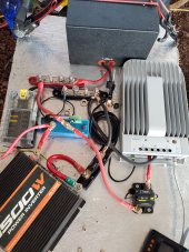
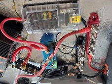
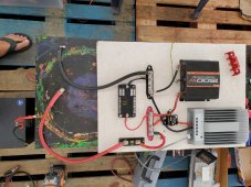
I have been trying to setup my offgrid solar system out here in Hawaii with 2 x 115AH LIFEPO4 Batteries. I thought I had the setup up to code with fuses etc. I did not have solar panels hooked up and wanted to test the system first. I did not hook up any loads to inverter. Everything was up and running, I programmed the charge controller and battery protect, everything working fine with battery level at 13.4V I flipped on the the power to the inverter and heard a pop and the Victron app said something about Circuit popped and started smoking until a fire was nearly created. Not sure what I did wrong but I could really use some advice on my setup. Pictures explain my setup. Thanks in advance