


You are using an out of date browser. It may not display this or other websites correctly.
You should upgrade or use an alternative browser.
You should upgrade or use an alternative browser.
Victron Smart Shunt - "correct" installation
- Thread starter bigmanonahill
- Start date
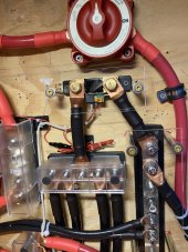
This is a pic of a blue sea classT with cover ,a 5 post Marinco BEP ( neg batt bus ) with its type cover.. …….and the clear ones are what I made for the 712 shunt and the 2 blue seas 8 post distribution buss bars out of 1/8 inch plexi cut to size needed..the stand offs are thick wall plexi tubing cut to fit the inside and 4 inch screws .. the are very strong and solid..No wiggle at all..I’d be interested of pics of the cover you put together.
Almost invisible in a pic ,very clear .cost probably about 2-3 dollars each ??? Mostly just the labor making them ..
overlook my 5000+ multiple screw holes in the plywood ,everything has been been moved many times trying to get the right fit and placement . The red dots signified if the fasteners had been torqued when finally assembled ..
Attachments
Hedges
I See Electromagnetic Fields!
- Joined
- Mar 28, 2020
- Messages
- 20,814
Battery fuse is in series with the shunt. So, how does it hurt if put before the shunt. Same current would still flow through them both.
If fuse was put between battery negative terminal and shunt, then if fuse blows, inverter sees Bat+ on it's positive input and shunt input is at -48V (assuming 48V system) relative to all other inverter connections.
If fuse it put between battery positive terminal and inverter positive input, shunt on battery negative terminal, then if fuse blows inverter sees Bat- on its negative terminal, shunt and all other inputs are 0V relative to Bat- and each other.
Depending on electronics design, having any inputs outside the range [positive input, negative input] can cause damage by backfeeding semiconductor inputs. Especially if those inputs are designed for say zero .. +5V, and you apply +48V or -48V.
Hopefully designed with high value resistors in series with both shunt inputs to protect electronics, but I have no idea what they did.
Just fuse both +Ve and -Ve (not approved / not acceptable in some jurisdictions and/or applications) if it does not go against local standards.If fuse was put between battery negative terminal and shunt, then if fuse blows, inverter sees Bat+ on it's positive input and shunt input is at -48V (assuming 48V system) relative to all other inverter connections.
If fuse it put between battery positive terminal and inverter positive input, shunt on battery negative terminal, then if fuse blows inverter sees Bat- on its negative terminal, shunt and all other inputs are 0V relative to Bat- and each other.
Depending on electronics design, having any inputs outside the range [positive input, negative input] can cause damage by backfeeding semiconductor inputs. Especially if those inputs are designed for say zero .. +5V, and you apply +48V or -48V.
Hopefully designed with high value resistors in series with both shunt inputs to protect electronics, but I have no idea what they did.
Last edited:
Pappion
Retired Engineer Tech
- Joined
- Nov 26, 2020
- Messages
- 552
JJJ, Smart Shunt "To Battery Minus" terminal should only be connected to battery -. Not sure why you have it connected to bus bar.
Also from the picture it looks like it's connected backwards.
Also from the picture there is no "VBAT +" wire. It needs that for power and voltage senseing.
Also from the picture it looks like it's connected backwards.
Also from the picture there is no "VBAT +" wire. It needs that for power and voltage senseing.
Last edited:
littleharbor2
Solar Addict
As long as we're on the subject I dug this out of my parts bin. Took it off of a system I dismantled. Who says you need a bus bar? ?


chrisski
Solar Boondocker
- Joined
- Aug 14, 2020
- Messages
- 5,246
With Class T fuses and holders that are 7 inches by 2.5 inches by 2 inches, double fusing becomes costly at $100 per fuse and holder and impractical, that is without adding in the cost for the 4/0 and 2/0 wire and lugs.Just fuse both +Ve and -Ve (not approved / not acceptable in some jurisdictions and/or applications) if it does not go against local standards.
I've found in practice double fusing is not that hard with smaller blade ANL fuses for low wattage devices, but rather impractical for larger high amperage devices.
Another reason for not fusing only the negative side with the normal negative ground build is leaves open a possible return route through chassis ground depending on how the system is wired. My RV is, and probably every RV and car out there is full of these paths if only the negative is fused.
Pappion
Retired Engineer Tech
- Joined
- Nov 26, 2020
- Messages
- 552
He has two batteries. I have 2 and no bus bar. 3 or more should have bus bar for Battery Minus.No reason not to mount smart shunt on -ve busbar. Victron website has sample designs/drawings with smart shunt mounted on -ve busbar.
littleharbor2
Solar Addict
Bus bars do make for easier maintenance and adding new loads. Stacking terminals on battery posts seems so crude once you get accustomed to bus bars. BTW my shunt is mounted on my neg. bus bar. Although not as clean as a nice factory made set, I make my own bus bars.He has two batteries. I have 2 and no bus bar. 3 or more should have bus bar for Battery Minus.
Correct. Same here. I don't support fusing of only the negative.Another reason for not fusing only the negative side with the normal negative ground build is leaves open a possible return route through chassis ground depending on how the system is wired. My RV is, and probably every RV and car out there is full of these paths if only the negative is fuse
Pappion
Retired Engineer Tech
- Joined
- Nov 26, 2020
- Messages
- 552
I know what a lynx distributor is. I can't imagine using it like that. It's like you don't care the use the fuses.
Similar threads
- Replies
- 2
- Views
- 165
- Replies
- 28
- Views
- 762
- Replies
- 1
- Views
- 308
- Replies
- 3
- Views
- 190