diy solar

diy solar

Victron. Want to hire an expert. Around SE.

Barryga

New Member
Joined
Feb 12, 2022
Messages
62
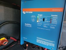
In short, I ordered a new super c motor home and ordered all Victron from battleborn; knowing nothing, I said send what I need.
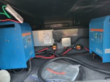
Included 2 3000 multiplexes and ordered 6 206 amps lithiums that Will tested
Put all on a pallet and shipped to RV dealer up north where motorhome was delivered.
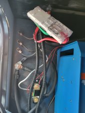
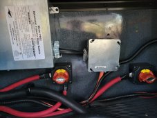
In 9 months works great, but the RV dealer installed a transfer switch, and im told I dont need it.
Im i. North Ga, but I can bring it to a nearby state.
I want to hire an expert, and if I dont need a switch that knows how to delete and wire up and look at the whole system and see if I need anything else added.
Bwk303@gmail.com
Thank you!
Barry in Georgia
 
As an alternative you could post pictures of your setup to this thread and the gang here could have a look.
 
I plan on it when light out in a few hours; thank you, sir!
Barry
 

Attachments

  • 20220212_084917.jpg
    20220212_084917.jpg
    196.4 KB · Views: 107
  • 20220212_084950.jpg
    20220212_084950.jpg
    125.9 KB · Views: 108
  • 20220212_084937.jpg
    20220212_084937.jpg
    320.6 KB · Views: 106
  • 20220212_084907.jpg
    20220212_084907.jpg
    249.8 KB · Views: 99
  • Screenshot_20220212-085029.jpg
    Screenshot_20220212-085029.jpg
    68.3 KB · Views: 103
Paging Dr @sunshine_eggo

My overall impression of the work is "sloppy".

I see...
2x Victron Multiplus 12 3000
The big wires are 2/0 awg but should be 4/0 awg... not an auspicious start.
Please post pictures of the over-current protection.

The automatic transfer switch is 120/240VAC

Solar charge controller is a Victron mppt 100/50
Please provide pics of that.

We see a bm712 battery monitor shunt.
All the joinery near the shunt bugs me.
There should be a high ampacity busbar here with a single bond to the chassis.
I fear they are using the chassis as a current carrying conductor to the batteries.
q: How far away are the batteries in relation to the shunt?
a:
Please post pictures of the batteries.

That un-secured plastic junction box with the green and red wire is not cool.

If you are confident you can do it safely please take pictures of the transfer switch and adjacent junction box with the lid off.

Please take a picture of the ac/dc distribution panel with the door open so that we can see the breakers, fuses and corresponding maps.

Do you have a generator?
If yes is connected via the main shore power inlet or some other way?

I imagine folks with better eyeballs will find more concerns.
 
Wow, im not good with electrical, so I hope I gave what you want.
The batteries are on the other side directly across from the Victron items, so maybe 8 feet.
Looked under by batteries and the Victron
But saw no ground.
The wire from fuse goes up to a generator and runs the microwave.
Generator Oan 8000 runs off diesel.
 

Attachments

  • 20220212_113236.jpg
    20220212_113236.jpg
    232.2 KB · Views: 98
  • 20220212_113337.jpg
    20220212_113337.jpg
    143.8 KB · Views: 96
  • 20220212_113402.jpg
    20220212_113402.jpg
    104.1 KB · Views: 89
  • Screenshot_20220212-113424.jpg
    Screenshot_20220212-113424.jpg
    117.8 KB · Views: 86
  • Screenshot_20220212-113438.jpg
    Screenshot_20220212-113438.jpg
    117.2 KB · Views: 85
  • 20220212_113230.jpg
    20220212_113230.jpg
    223.9 KB · Views: 99
  • 20220212_115413.jpg
    20220212_115413.jpg
    294.1 KB · Views: 85
  • 20220212_115426.jpg
    20220212_115426.jpg
    232.3 KB · Views: 92
Last edited:
The wire from fuse goes up to a generator and runs the microwave.
OMG that fuse is going to burn down your RV. It looks like one fuse stud is bent badly and the wire lugs aren't even touching the fuse.

The parallel wiring of the 6 batteries is horrific. Those batteries are not going to stay balanced at all. 6 batteries in parallel really need to be wired with bus bar and equal length connections from each battery to the bus bars.

It's clear that the people that did your electrical system don't care at all about doing quality work. That was a "do it fast, do it cheap, just make it barely work" job. I wish you luck getting this all worked out.
 
Thank you, sir; I can restore your car build your engine, or write a formula for a new product related to paint, but never learn electrical; this is why im trying to find someone around Georgia I can hire to make it the way it should be.
I have had no luck finding someone.
As far as cheap, I told the dealer ship I did not want a price. Just do it like you would if yours.
 
I agree with everything @rmaddy said above.

Lets do the math on the main dc circuit.
Lets pretend 3000VA is actually 3000 watts
Lets pretend the inverter efficiency is .85 even though it is higher.
The errors tend to cancel each other out.
3000 ac watts / .85 conversion factor / 12 volts low cutoff = 294.117647059 service amps
294.117647059 service amps / .8 fuse headroom = 367.647058824 fault amps.
That means 4/0 awg and a 400 amp fuse for each inverter.

I'm sorry that this has happened to you.
I would be very ashamed if I had done this install.

And we have not even gotten to the transfer switch.
 
@rmaddy can you tell if they are using the chassis for negative return?
I would not be surprised.
 
@rmaddy can you tell if they are using the chassis for negative return?
I would not be surprised.
I can't make out the wiring at all. Since the wires are such a jumble and going between compartments and disappearing behind other items, I'm unable to follow where anything is going given the current pictures. I think it's going to take someone onsite to work up a full schematic given the realities of trying to trace everything.
 
Thank you, guys; the first picture from the battery fuze going to box side
The following picture is on the box side.
The following picture is where both reds go
The black goes to the first inverter, and the following picture shows black from the inverter goes to a junction of some sort.
 

Attachments

  • 20220212_130512.jpg
    20220212_130512.jpg
    144.6 KB · Views: 35
  • 20220212_130636.jpg
    20220212_130636.jpg
    83.3 KB · Views: 34
  • 20220212_130957.jpg
    20220212_130957.jpg
    342.2 KB · Views: 35
  • 20220212_131003.jpg
    20220212_131003.jpg
    378 KB · Views: 36
Thank you, guys; the first picture from the battery fuze going to box side
The following picture is on the box side.
The following picture is where both reds go
The black goes to the first inverter, and the following picture shows black from the inverter goes to a junction of some sort.
@Barryga I'm still not sure what I'm looking at, partly due to my poor eyesight.
Please locate the main negative cable of the batteries and see where it terminates.
My guess is it will be bonded to the chassis in the battery compartment, confirm?
 
Black goes from the battery to the other side and connects to the top. The bottom black comes from the first inverter.
Then in the second picture is where goes next?
A body ground?????
I have two gauge, should I gound that connecter to frame? It's an international frame so; not afraid to drill a hole.
 

Attachments

  • 20220212_133741.jpg
    20220212_133741.jpg
    193.5 KB · Views: 22
  • 20220212_133756.jpg
    20220212_133756.jpg
    191.3 KB · Views: 24
Last edited:
Wires are, as said, too thin for these massive inverters

Also, using electrical tape on the lugs? Should have used proper heatshrink to make it a clean install

Also, Charged voltage in the BMV set to 14.7V? In that setting, 100% reset is never done since the batteries shutdown at 14.6V.
And its generally recommended not to go to 14.6V anyway
Fixing now.
Thanks
 
Black goes from the battery to the other side and connects to the top. The bottom black comes from the first inverter.
Then in the second picture is where goes next?
A body ground?????
I have two gauge, should I gound that connecter to frame? It's an international frame so; not afraid to drill a hole.
I still can't make sense of the pictures or your description.
Maybe someone else can translate from English to English.
 
Also, Charged voltage in the BMV set to 14.7V? In that setting, 100% reset is never done since the batteries shutdown at 14.6V.
And its generally recommended not to go to 14.6V anyway
Good catch. I hadn't looked at the BMV battery settings screenshot. I've been told that the BMV's "Charged voltage" setting should be 0.1V lower than the "Absorption voltage" setting of the charger. For SOK batteries I would charge them at 14.2V absorption and 13.5V float and set the "Charged voltage" to 14.1V.
 
Good catch. I hadn't looked at the BMV battery settings screenshot. I've been told that the BMV's "Charged voltage" setting should be 0.1V lower than the "Absorption voltage" setting of the charger. For SOK batteries I would charge them at 14.2V absorption and 13.5V float and set the "Charged voltage" to 14.1V.
Done!
 
Anything else I should change until I find a pro to work on it.
 

Attachments

  • Screenshot_20220212-140320.jpg
    Screenshot_20220212-140320.jpg
    117.1 KB · Views: 8
The rest of the BMV settings look fine. You might want to post the solar charger battery settings.
I just unplugged the motor home so I can let the battery run down won't take long with the fridge on and electric heater on at 1500 watts
 

Attachments

  • Screenshot_20220212-141120.jpg
    Screenshot_20220212-141120.jpg
    107.9 KB · Views: 6
I just unplugged the motor home so I can let the battery run down won't take long with the fridge on and electric heater on at 1500 watts
That's not the solar battery settings. Tap the gear icon on the top right and then go to the Battery settings.
 
The reading on the ac/dc panel is hard to read but I think the second breaker from the left is labeled "inverter".
I'll bet that actually means converter and I notice it is on.
I further guess it means there is no 12 volt feed from the batteries.
From which I further guess that the converter is being powered by an inverter which means the efficiency will be just pathetic.

In that case the core system should have been 24 or 48 volts.

@Barryga if you turn off the second breaker does your dc power go away?
 

diy solar

diy solar
Back
Top