Ejimenez
New Member
Panel specs are
Vmp: 34.9v
Imp: 13.19A
Voc: 41.8v
Isc: 13.92A
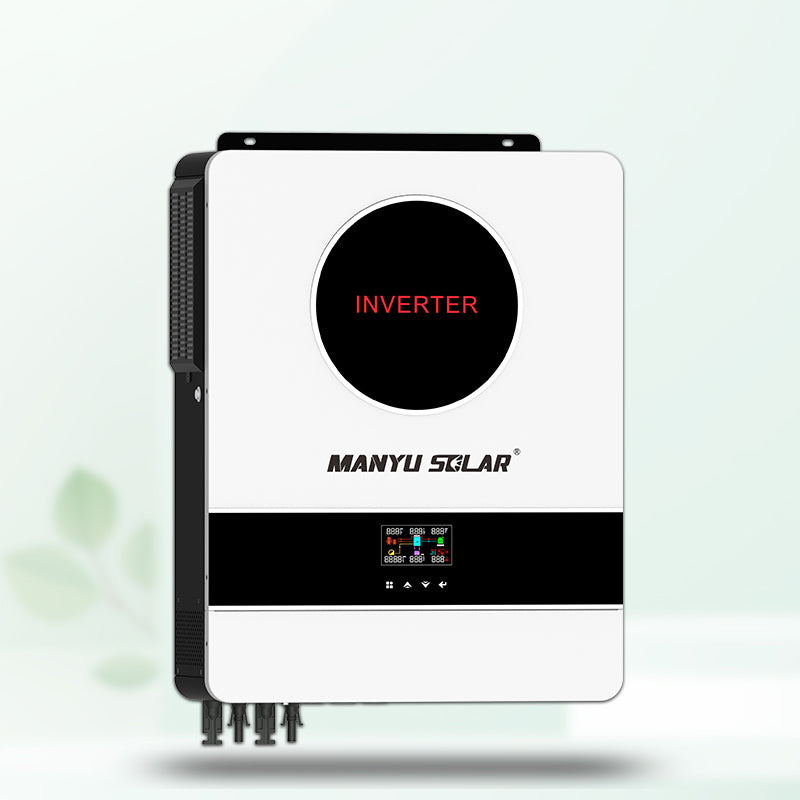
If im not mistaken inverter is rated for a MAX of 500VDC and MPPT voltage range of 90-450VDC, it says number of MPPT/Maximum Input Current is 1/27A.
im going for 18 of those panels so I am assuming I can make 2 9 panel series and then both series connect them parallel and thus would give me around (Using Voc) 376.2V and 26.38A which would work fine for the inverter specs right? (I assuming with cabling loss and temps of 80+(even 100F) would lower those values a bit more no? Do I need to consider isc with voc or its just voc with imp? If I use voc and isc for the calculation it would pass 27a easily. Would it be better to just upgrade the inverter to be safe? (im not doing this DIY but would like to be safe of what the installer/company is doing lol)
Vmp: 34.9v
Imp: 13.19A
Voc: 41.8v
Isc: 13.92A
If im not mistaken inverter is rated for a MAX of 500VDC and MPPT voltage range of 90-450VDC, it says number of MPPT/Maximum Input Current is 1/27A.
im going for 18 of those panels so I am assuming I can make 2 9 panel series and then both series connect them parallel and thus would give me around (Using Voc) 376.2V and 26.38A which would work fine for the inverter specs right? (I assuming with cabling loss and temps of 80+(even 100F) would lower those values a bit more no? Do I need to consider isc with voc or its just voc with imp? If I use voc and isc for the calculation it would pass 27a easily. Would it be better to just upgrade the inverter to be safe? (im not doing this DIY but would like to be safe of what the installer/company is doing lol)