diy solar

diy solar

Voltage spike before a wiring bottleneck

Flyview

New Member
Joined
Apr 30, 2020
Messages
18
Hoping you guys can help me understand a couple of things!

I have a Victron 75/15 solar charge controller that I know I undersized the output wires for (16AWG). I will be upgrading that soon to 10AWG (although I've found only 12AWG actually fits in the controller), and probably the whole controller to a 100/20 as well since I've added another panel (300W total).

I want to understand 2 things:

1) It seems like electricity flowing doesn't work quite like water flowing in a pipe. A very short length of thin wire (for ex a fuse) does increase the overall resistance a tiny bit, but it doesn't seem to restrict the flow for the overall length of the remaining wire, if the rest of it is thicker. Is this correct? So I could attach a small length of fused 12AWG to the output of the controller and then link that with 10AWG or thicker to the battery?

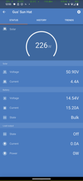
2) Right now with the undersized controller to battery wires, the controller is seeing a higher voltage on the output (battery) than the rest of my system. For example, the controller is reporting the battery voltage at 14V while charging at 160W. The rest of my system (based on a simple voltmeter reading) is actually at 13.5V, and my battery is maybe at 13.35V. I assume that the thicker wires I go, the less voltage will "build up" at the controller along the wire on its way to the battery. Is this correct? In my current setup, how much of that "14V" is lost to resistance through the 16AWG wire if the circuit is actually at 13.5V after the bottleneck? If I reach the 15A limit of the controller now, it shows 222W (14.8A x 15A). Does that mean the reality is more like 13.5V x 15A = 203W?

I just wanna understand how this works! Thanks!!!
 
Last edited:
0.5V sounds like a connection issue or a controller fault.

Ensure you have no loose connections and are using proper fine strand wire at the MPPT.

Measure battery connection AT the MPPT with voltmeter and compare to VictronConnect output.

Also good go check at night when you have no current flowing.

Everything is super tight. I know, because when it wasn't it was even worse. At night the voltage reported by the controller is accurate. It only goes much higher during charging and gets worse as solar gets more powerful. You don't think it's the undersized wires? Basically same thing as a "connection issue".

I should also mention that the 16AWG wires (about 3-4 feet long) don't go directly to the battery, but into another 10AWG circuit that eventually goes to the battery. The positive is soldered into that circuit but the negative has a crimp ring terminal that is bolted to the chassis. I suppose this one MAY be loose as it's out of reach and the crimp terminal I used I have found over time in other places to not be great. I will check this soon.
 
Last edited:
Everything is super tight. I know, because when it wasn't it was even worse. At night the voltage reported by the controller is accurate.

Then there's not an error at the MPPT.

It only goes much higher during charging and gets worse as solar gets more powerful. You don't think it's the undersized wires? Basically same thing as a "connection issue".

Yes. 15A requires 14awg minimum. Thicker may be required due to distance to battery.

I should also mention that the 16AWG wires (about 3-4 feet long) don't go directly to the battery, but into another 10AWG circuit that eventually goes to the battery. The positive is soldered into that circuit but the negative has a crimp ring terminal that is bolted to the chassis. I suppose this one MAY be loose as it's out of reach and the crimp terminal I used I have found over time in other places to not be great. I will check this soon.

Upgrading to 10awg should help, but resolving any potential connection issue (crimps included) is important.


Indicates 14V @ 15A through 16awg 4' long will lose about 0.5V.
 
It seems like electricity flowing doesn't work quite like water flowing in a pipe. A very short length of thin wire (for ex a fuse) does increase the overall resistance a tiny bit, but it doesn't seem to restrict the flow for the overall length of the remaining wire, if the rest of it is thicker. Is this correct?
It's actually the same way for water.

If you have 50ft 1" + 50ft 1/2" it will have lower resistance than 100ft of 1/2".

For this reason, even if you have a 5/8ths water service, it can still be worthwhile to run 1" pipe behind the meter for better flow.

The energy lost is a factor of the voltage drop, if you lose .5v at 15 amps that's .5x15=7.5 watts of heat coming off the wire.

Hmmm interesting, but to compare with the fuse analogy, if you restrict a 1" diameter pipe down to 0.02", even over a distance of one inch, wouldn't that basically "clog" up the rest of the pipe?
 
wouldn't that basically "clog" up the rest of the pipe?
Yes but only proportionate to the length of the construction. If you restrict it to .02" for 1" vs. .02" for 18" the former will flow a lot better than the latter.

There is also the fitting head, where the transitions from 1" to .02" itself adds resistance. I don't think electricity has a fitting head, so that's where the analogy starts to break down.
 
Then there's not an error at the MPPT.


Yes. 15A requires 14awg minimum. Thicker may be required due to distance to battery.


Upgrading to 10awg should help, but resolving any potential connection issue (crimps included) is important.


Indicates 14V @ 15A through 16awg 4' long will lose about 0.5V.
Thanks!

So does this mean I am also losing 0.5V x 15A = 7.5W of power or not really because that 14V wouldn't be 14V with a thick cable? I assume with thicker cables the current would remain the same but the voltage would drop on the controller side. How do I calculate how much power I am actually losing because of the undersized wires?

In the example, you are losing 7.5W of power heating the wire.

You will lose less with thicker cable.

You have correctly calculated power loss.
 
Yes but only proportionate to the length of the construction. If you restrict it to .02" for 1" vs. .02" for 18" the former will flow a lot better than the latter.

There is also the fitting head, where the transitions from 1" to .02" itself adds resistance. I don't think electricity has a fitting head, so that's where the analogy starts to break down.

Here's what I'm seeing in my head:

Wire:
10ft 10AWG wire -> 1" 0.5mm fuse - > 10ft 10AWG wire.

Flows almost as good as without the fuse, correct?

Water:
10ft 1" pipe -> 0.02" restriction (calcium rock the width of an inch) -> 10ft 1" pipe.

Are you saying the flow at the end of the pipe would be almost as good with the rock blockage as it would without it there?
 
In the example, you are losing 7.5W of power heating the wire.

You will lose less with thicker cable.

You have correctly calculated power loss.
I appreciate your help! Is it also accurate to say that the power reported by the controller is also inaccurate due to it seeing a higher voltage? For example, I saw it maxed out at 14.54V @ 15.2A = 221W, but with a thicker cable, this might be 13.8V @ 15.2A = 210W. Which one is correct?

Edit: Actually, I'm not sure how the controller calculates the "solar power" displayed. It may be the power on the solar input side not the output. Here's a screenshot of the real world example.
 

Attachments

  • Screenshot_20240221-125547.png
    Screenshot_20240221-125547.png
    99.6 KB · Views: 2
Last edited:
Are you saying the flow at the end of the pipe would be almost as good with the rock blockage as it would without it there?
Diameter wise, that would be more like a .20"/1" comparison, rather than .02"/1".

But still not saying that because plumbing has fitting head, which electrical doesn't, you don't get turbulent electron flows, and I don't know if plumbing head scales to pipe diameters the same way that resistance scales to copper diameter.

The ultimate point is just that bottlenecks are proportionate to the length of the constriction.
 
I appreciate your help! Is it also accurate to say that the power reported by the controller is also inaccurate due to it seeing a higher voltage?

No. That's actually the power it's delivering at its output terminals. The issue is the wire is losing power between the MPPT output terminals and the battery.
 
No. That's actually the power it's delivering at its output terminals. The issue is the wire is losing power between the MPPT output terminals and the battery.

Did you see my edit above with the real world screenshot? The voltage reported would go down with a thicker wire wouldn't it? Would the current go up in that case (assuming there was no 15A cap)?
 
If I read correctly. You are using the chassis for part of the charging circuit. (Negative)
I would replace this with an actual conductor.
 
Did you see my edit above with the real world screenshot? The voltage reported would go down with a thicker wire wouldn't it? Would the current go up in that case (assuming there was no 15A cap)?

That doesn't change my response. The power reported by the MPPT is the output of the unit. What gets to the battery is less than that. If there are no wiring losses, the MPPT power output will be what the battery/system receives.
 
Another option is using a victron smart shunt via virtual network, it sends the actual battery voltage to the SCC and takes care of any wiring losses.
 
Another option is using a victron smart shunt via virtual network, it sends the actual battery voltage to the SCC and takes care of any wiring losses.

It removes a complication of wiring losses, but not losses themselves.

Wiring losses will still be present, but they will not cause the MPPT to transition from bulk to absorption prematurely based on wiring loss. If the MPPT terminals are measured, they will still report the elevated voltage. The power reported will be the actual power delivered to the battery, not what is actually output by the MPPT.

But I fundamentally agree with the recommendation. :)
 
Should have been more clear, takes care in calculating an output voltage at the MPPT terminals to get the desired result at the actual battery terminals. Which is quite key in 12v systems when dealing with lifepo.

You can’t remove the loses only manage how they factor into your system.

Good news too the smart shunt dropped prices recently too!!!
 
Back
Top