diy solar

diy solar

What should the fully charged at rest voltage be?

edweather

New Member
Joined
Oct 17, 2023
Messages
78
Location
Camden County Georgia
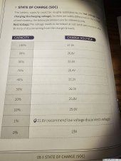
I'm using a Time USB 25.6V 200Ah battery. My AIO inverter is Mpp PIP 2424LV-MSD. Have been charging the battery with one 375W panel during basically cloudy conditions for the past 2 days. The charge controller on the inverter blinks green when charging, and goes to solid green when charged. It's been blinking since yesterday, and is solid green now but the battery voltage is 26.2V. That seems low. The battery icon on the display shows 50% charged. Trying to find out what the at rest voltage should be fully charged. The battery manual shows a charge voltage of 27.0 at 100% capacity. Is that the same as the at rest voltage? My only thought is that the one panel on a cloudy can't charge it properly, but just a guess.
 

Attachments

  • 20231203_171632.jpg
    20231203_171632.jpg
    670.8 KB · Views: 5
Last edited:
Voltage vs. State of Charge is not very accurate unless its at the very top or bottom portion of the curve where the relationship becomes more vertical.

Normal resting voltage for a fully charged LFP cell is 3.35V. For an8 cell battery that is 26.8V. So 26.2V is a little low but could be a discrepancy between actual battery voltage and what the inverter is reading. Not sure if that brand has a way to you can calibrate DC batt voltage. Have you checked with a meter?
Thanks. Yes checked with a meter and it agrees with the inverter at 26.2. What bothers me is that the battery icon on the inverter shows 2 out of 4 bars. The difference between 28.8 and 26.2 is about 50% battery charge according to the chart in the battery manual.
 
Fully charged LFP cell has an unloaded rested voltage of 3.43v. But that is not the whole story.

When you fully charge at 3.43v to 3.65v per cell absorb voltage until charge current tapers off there will be a surface capacitance charge that builds up on internal layers, mostly associated with negative graphite electrode. This capacitance charge has insignificant capacity and will burn off quickly upon some slight discharge current. The surface charge will bleed off on its own after a few hours to a couple of days of no load on cell.

Unloaded, rested cell voltage is pretty accurate, but you also need an accurate DVM of better than a couple of mVdc accuracy at 3.5v. That is better than 0.05% accuracy for DVM. At full charge state, you also have to be sure there is no surface charge. It is hard to be certain of this until a cell open circuit rested voltage drops below about 3.35v. Cell temp has little effect on open circuit voltage but is very significant when cell current is present for discharging or charging.

LFP Open Circuit Voltage vs SoC.png
 
If the inverter is on, is the battery really resting? Or is the inverter drawing from the battery?

Normally you would disconnect the battery and let it sit before taking the resting voltage.
 
If the inverter is on, is the battery really resting? Or is the inverter drawing from the battery?

Normally you would disconnect the battery and let it sit before taking the resting voltage.
Depends on inverter, but likely not be zero battery current. Also has to be zero current for at least about 5 minutes to ensure equilibrium on cells.

Just a very small amount of cell current will affect cell voltage +/-10mV to +/-20mv. That is why just passively paralleling cells will not fully balance their state of charge.
 
Cell voltage recovers and achieves equilibrium again from a cell current discharge. It takes about 90 seconds to 5 minutes to fully recover depending on cell condition, previous cell current, SoC condition, and cell ambient temperature.

The delay is mostly due to electrolyte achieving charge balance equilibrium from the lithium-ion migration charge balancing through electrolyte.

Demanded cell current creates an overpotential voltage gradient through electrolyte that drives the lithium-ion migration from the dissolved lithium salt in electrolyte. The amount of overpotential voltage at given cell current and cell temp is a good indication of cell quality. It is temp dependent and increases at colder cell temps.

Lithium hexafluorophosphate (LiPF6) salt, is dissolved into ions (Li+) and cat-ions (PF6+) in the electrolyte solvent mix of Ethylene Carbonate C3H4O3 (EC), and Dimethyl Carbonate C3H6O3 (DC). The Li+ ions dissolved in electrolyte are only for transport. Electrolyte is the transport conveyor belt for lithium-ion charge between positive electrode (LFP) and negative electrode (graphite). Electrolyte is charge neutral at no load, equilibrium open circuit voltage.

Overpotential slump with load current.png

Li-Ion Graphite battery model.jpg

NMC NCA LFP LTO celll electrodes potential.png
 
Last edited:
So with the help of another thread I figured out how to use the Utility charger portion of the inverter. With charging amps set at 40 it really brought up the charge of the battery. Really made a huge difference compared to my two panels. Battery at rest now at 27.2V which is 100%. ?
 
Last edited:
Back
Top