diy solar

diy solar

What wire gauge to use?

Sam S

New Member
Joined
Feb 11, 2023
Messages
5
Location
South Australia
Hi all,

My name is Sam and I could use your help determining the appropriate wire gauge for my power station.

I am working on a portable power station with the following specs:
  • 200Ah lifepo4 battery
  • 2000w inverter
Atm, I am only concerned with the wire that will go from the:
  • battery > fuse
  • fuse > fuse block
  • fuse block > BMS, and
  • battery > inverter
I have tried several wire gauge calculators (jCalc, Energy Matters and Ayixa) and a couple cable size charts (battery story and enerdrive) however I am still unsure.

To help you assist me, I will run you through my thought process thus far:
  1. For a load of 2000W, the current drawn from the battery (by the inverter) will be 200A (2000/10, according to Redarc).
  2. Further, my inverter has a surge capacity of 4000W. This, I think, means that the wire needs to handle up to 4000W. So 400A (4000/10).
  3. However (using jCalc), a 2000W load is divided by the voltage (12V) to calculate the current. That is: 167A (2000/12).
  4. Further, surge 4000/12 = 333A.
  5. As you can see, I've come across two different ways to calculate the current.
  6. If I go with jCalc's method of calculating current then I use Energy Matters' wire gauge calculator:
  7. I get: 24.4488 mm2 wire cross section (by plugging in 12V, 167A and 1m wire length) and 48.7512 mm2 (12V, 333A and 1m).
  8. However when using the enerdrive's cable sizing selection chart I get different results. For example, a wire length 0-8m up to 200A calls for a 67.5 mm2 wire cross section in this chart.
  9. So I am unsure whether I need 2AWG, 0AWG, 00AWG or potentially higher.
  10. Finally, I do not know if I need the same gauge (or varying) for the wiring that I am only concerned with at this moment.
Thank you for taking the time to read my post.

Any insight you can offer would be most appreciated.

~Sam :)
 
Last edited:
You should spec the wire for the continuous service, not the surge. Surging typically lasts only for 500 miliseconds or so, so the wire can't get hot enough it that short amount of time.

Whether or not your inverter can actually put out 2000W continously is questionable. Many of the lower-cost (cheapo) manufacturers are overly generous with their ratings, to make the ad look better.

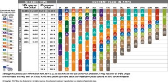
Here is a ampicity chart to guide you. More likely than not 000 wire will be sufficient. That is what I myself am using for my 4000W 24V inverter.
 
Option C: None of the above.

2000 watt / 12 volt / .94 inverter efficiency = 177 amps.

Plug 177 amps at 12 volts and the round trip length into a wire gauge calculator and you should arrive at a wire size. I used 10' for a distance and the wire gauge calculator that I prefer says 2 AWG is what should be used. A LiFePO4 battery is dead, dead, dead at 10 volts. Nobody around here uses 10 volts in the wire gauge calculation. 12 volts is the norm, but if you plan to run your battery down to a much lower state of charge you should use a lower voltage in the calculation. If you have control over the low voltage cutoff in the inverter and the BMS then you can use the more conservative 12 volt number.


You are always welcome to upsize the cable to give you added peace of mind.
 
i'm buying solar equipment for my kid sister, who lives in an area with frequent outages. I bought a renogy 3000w inverter, and will be connecting the 259WH battery about 10' away. she'll probably be running a 700w fridge, usb lights, and some computer stuff. heating is propane.

the most draw is likely the fridge compressor startup. I'm really confused as to what gauge copper wire I need to connect the inverter to the battery, and what amp anderson-type connectors to use. I've read the information in this thread, but as we all know, information < knowledge << wisdom.

any wisdom???
 
Is this a 12 volt, 24 volt, or 48 volt system?

Big difference in wiring.

I don’t think you mean 259 Wh. This is not close to running a 700 watt load very long.

Inverter should be as close to the battery as possible, and the rest of the 10’ would be the AC Run.
 
i'm buying solar equipment for my kid sister, who lives in an area with frequent outages. I bought a renogy 3000w inverter, and will be connecting the 259WH battery about 10' away. she'll probably be running a 700w fridge, usb lights, and some computer stuff. heating is propane.

the most draw is likely the fridge compressor startup. I'm really confused as to what gauge copper wire I need to connect the inverter to the battery, and what amp anderson-type connectors to use. I've read the information in this thread, but as we all know, information < knowledge << wisdom.

any wisdom???

The idle draw on the Renogy 3000W is going to kill your battery fast. It’s also way too big for the loads your sister will be running (see my note on assumption on the fridge below.) I had the 2000W version and had to ditch it for the really high idle draw.

I assume the fridge doesn’t use 700W continuously. Old ones sometimes use that much but newer ones use 60-200W. How did you determine the fridge uses 700W?

We have nearly the exact same use case as your sister. Except our fridge uses 800W to startup for 2.7 seconds, then immediately settles to 60-90W. We now use a 1000W Victron inverter and it works perfectly. It powers the fridge, two laptops, some lights and occasionally a heated blanket, never misses a beat The surge is a real surge ability: 2400W for up to 30 seconds, unlike the Renogy which is less than 1 second. Most devices with start up surge need 2-5 seconds of surge time.

With the big idle draw of the 2000W Renogy, it was using over 50% of our battery per day. The 3000W model would’ve been much worse. If we had a single cloudy day, we were screwed. We didn’t have the budget for more panels at the time, but the inverter sucking down the battery was worse than not enough panels. The Victron uses about 15% of our battery on eco mode. Even without more panels (we do have a couple more now), this gives us enough battery to get through 52 hours in cloudy weather (and shaded, almost zero production).

As for USB charging, I installed one of these and I love it. Charges things fast and no efficiency loss since it’s connected directly to 12v:

Dual USB Quick Charge 3.0 Port & PD USB C Car Charger Socket, 12V USB Outlet with Voltmeter and Power Switch for Car Boat Marine Truck https://a.co/d/cjzUIoT
 
i'm buying solar equipment for my kid sister, who lives in an area with frequent outages. I bought a renogy 3000w inverter, and will be connecting the 259WH battery about 10' away. she'll probably be running a 700w fridge, usb lights, and some computer stuff. heating is propane.

the most draw is likely the fridge compressor startup. I'm really confused as to what gauge copper wire I need to connect the inverter to the battery, and what amp anderson-type connectors to use. I've read the information in this thread, but as we all know, information < knowledge << wisdom.

any wisdom???

Also, if you really do intend to use that 3000W inverter, you might like to know that 3000W is at the top end of what is realistic to run on 12v. You need some massive cables between the inverter and battery. Expect to pay about $90 for a pair of 6-foot 2/0 cables.

And like i I said before, 3000W is way overkill for your sister’s needs, unless that fridge is truly 700W continuous. If so, then the startup surge of that fridge could be a high as 7000W and it won’t run even on a 3000W inverter with a surge rating of 6000W of less than 0.5 seconds.

By the way, the surge rating on these cheap inverters like what Renogy sells is useless. It’s for marketing only. It won’t help you if you need a surge, because less than a second of surge ability isn’t long enough to power anything you’d want it for. Not a fridge, power tool, or anything with an electric motor. So you buy a cheap inverter for its continuous rating.

First priority is to find out the actual running watts and startup watts of that fridge. Use a killawatt meter to find the running watts. Sometimes the killawatt is fast enough to catch the startup surge, but not always. Take the highest running watts number and times by 10 to estimate the startup surge. It’s a conservative estimate but in my experience is pretty accurate.
 
Transient surge should not be something you design for, as that is very transient. If we designed all of our systems for max spikes, we'd be using cable the size of a D battery! LOL According to the calculator I use 00 (2/0) should work fine if you're only going 10 feet away. Here's the calculator. This gives you a tad over 2% voltage drop at 10 feet with 12V and 167 amps. Specifically it says you can go 18.44 ft (that's the roundtrip distance, so 9.22 ft) and only have 2% drop. 3/0 would be overkill in my opinion and much more expensive.
I love how you can choose the voltage drop you're willing to live with. 2% is a great target. The majority of solar installs have at least 5%.
https://www.wirebarn.com/Wire-Calculator-_ep_41.html
 
Last edited:
First priority is to find out the actual running watts and startup watts of that fridge. Use a killawatt meter to find the running watts.

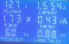
I just tested a typical 18 cu ft single door and top freezer refrigerator.
The compressor was using 1.55 A and the measured consumption was 173 W with a 0.88 Power Factor

20231219_004606.jpg

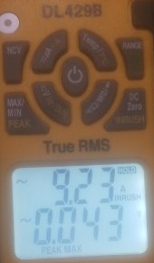
About the surge rating, I measured a 9.23 A In Rush courant (or 6x the nominal 1.5A)
The Inverter would need then to handle about 1 kW of In Rush Power (for a 0.88 PF).

20231219_005708.jpg

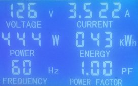
Don't forget to add in the total consumption the automatic defroster's heating element which might be activated about every 12 hours
and might requires another 400W, but the duration depends on the thermostat setting. However the compressor and the defrost heater
will not be running at the same time. (See picture showing 444 W used by the defroster.)

20231219_004521.jpg

i' will be connecting the 259WH battery ... running a 700w fridge,

I think you mean a 259 Ah battery cells, so under 12 V you would get about 3.1 kWh, but you can only use about 80% or 2.5 kWh.
You didn't mention how you plan to charge the battery, such as using Solar Power or the GRID like an UPS?

Looking at the values above, my reported consumption for the past month was 43 kWh, or 1.4 kWh a day, or 120 Wh per hour.
If I was using a 12V DC to 120V AC Inverter, with a 90% conversion efficiency, the battery consumption would be arout 1.6 kWh a day.

The idle draw on the Renogy 3000W is going to kill your battery fast.

With the big idle draw of the 2000W Renogy, it was using over 50% of our battery per day.
The 3000W model would’ve been much worse.
The Victron uses about 15% of our battery on eco mode.

By just doing a napkin-table calculation, let estimate that the Inverter consumption without any load would be 20 W for a 2 kW inverter.
(There are some threads dealing with this issue, such as: Idle 'no load' Consumption - Specs vs Your Personal Observation)
So over a 24 hours period, the overall additional consumption requires to keep the Inverter running would be 480 Wh.

In my personal case, the daily consumption would be 1.6 kWh for the fridge and 480 Wh for the Inverter, or about 2 kWh a day.​
So the above example of 259 Ah battery, with 2.5 kWh available, would be conceivable, if the outage lasts less than a day,​
unless the battery could be recharged with Solar Energy.​

Note: I wonder if it would be more efficient to turn off the Inverter when the fridge is not running
and use a relay with a delay to connect the fridge after re-starting the Inverter.

The USB light and laptop computer could be directly connected to the battery for better efficiency.

the most draw is likely the fridge compressor startup.
I'm really confused as to what gauge copper wire I need to connect the inverter to the battery, and what amp anderson-type connectors to use.

Going back to your initial concern regarding the wires required to connect the Inverter to the 12V battery,
you need to determine what will be your fridge consumption and In Rush Power.

In my personal case, using a 18 cu ft single door and top freezer refrigerator, beside the 1 kW In Rush Power,​
the compressor consumption was 173 W (or 194 VA with a 0.88 pf) and 444 W (or 444 VA) for the Defrost.​
To get about 500 VA with a 90% Inverter efficiency, the steady current would be around 45 A.​
While in the case of the 1 kW In Rush Power, the surge current would be around 90 A.​
By just looking at the Chart in the above #9 posting, for a wire up to 10 ft,​
a 6AWG could handle 50 to 70 A and a 4AWG could handle 80 to 100 A.​
In general, the Inverter should be installed next to the battery,​
so the wire could be only one to three feet long.​
 
Last edited:
I don't think that most installations have anywhere near a loss of 5% between the battery and inverter. Mine is about .2% at peak current.
What's your current and cable length between the battery and inverter? For short runs I think you're right, but anyone going 20 or more feet is not going to have only 0.2% unless they're running massively oversized cables. If your inverter is sitting next to the battery that's possible, but if it's say more than 5 feet away it's not going to be 0.2% without gonzo cable sizes. A 2/0 cable running 200A @ 12VDC can only go 7.7 ft (roundtrip length of the cable) at 1% voltage drop. For a 0.2% drop you would need bigger than 4/0 - you would need a cable size that is in the MCM range.
 
Last edited:
What's your current and cable length between the battery and inverter? For short runs I think you're right, but anyone going 20 or more feet is not going to have only 0.2% unless they're running massively oversized cables. If your inverter is sitting next to the battery that's possible, but if it's say more than 5 feet away it's not going to be 0.2% without gonzo cable sizes. A 2/0 cable running 200A @ 12VDC can only go 7.7 ft (roundtrip length of the cable) at 1% voltage drop. For a 0.2% drop you would need bigger than 4/0 - you would need a cable size that is in the MCM range.
195 amps, 18 inches of 2/0 to the bus bar, and batteries individually connected with number two. I’m also running at 48 volts nominal.

I just think the op is justifying high losses by saying “but everybody does it.”
They don’t. I’d re-evaluate a design that calls for 20 foot runs carrying 200 amps.

If you’re using a system a lot, large conductors are more economical. And higher voltages.
 
Back
Top