diy solar

diy solar

Why is my voltage dropping

I will guess that your "problem" consists of the controller switching between MPPT and PWM mode, very likely inspired by setting "Boost Voltage" and "Float Voltage" the same. Your "Boost Return" Voltage is also a significant parameter WRT the operation of the MPPT controller.

In PWM mode, the rapidly cycling "straight-through" connection pulls the measured PV voltage down, to be only slightly above the desired battery charge voltage. While the batteries become more charged, the proportion of "disconnected" time increases, and PV voltage being shown will tend to increase. It is IMO an error of design to show "PV Voltage" from the connected state value, but that seems to be what it's doing.

This was SWAG, of course. In this scenario, the fact that only 2-3 watts of power was being pulled was probably also a factor in the controller abandoning MPPT mode.
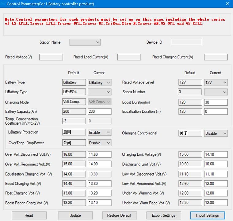
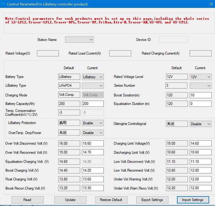
Thanks for that. I didn't know it switched to PWM mode at all, but could explain what is happening.

It seems to be very fussy with the settings, i'm not even sure the boost/float works very well. It seems to go into "float" charge mode but still continue to supply current to the batteries when they are not full.

They appear to do that based, not on the battery voltage, but the charge voltage, but do eventually float when the battery is full.

I am not sure the controllers are as well designed as they could be.
 
Fuzzy logic programming. LOL
Now if you leave it there it is likely to not reset down to a lower voltage on the PV input, unless it's dark. At least that's how mine worked.

I have two programs - one for long term storage with lower values that lets the battery drift down between 50 and 80% SOC, then a more aggressive one that keeps them charged up for daily use.

I find the boost and float works perfectly, you just have to get the values set that give you the results you want. I have fiddled with mine for hours on end, low and high charge, duration, charge voltages, to get my battery to do what I want it to do.

Off Grid Garage is a mildly funny solar guy on YT that has done extensive testing with all the values. Lifepo4 has such a flat charge/discharge voltage curve that it throws off the solar controllers - you have to enter numbers that get you what you want.

Here are my two charge parameters that give me exactly what I want and work perfectly. I'm not saying anyone in particular should use them, everyone needs to find what works for their setup. Mine is a 230A prismatic DIY pack in a motorhome.

I also have a second Tracer mppt 1206N for a pair of folding portables. It's settings are left on factory default for lifepo. It goes to float before the bigger charger due to charge voltage - these controllers read battery/system voltage with their charge current on top. Both of my controllers consistently read battery voltage about 200mA higher than the actual battery voltage. So I have to take that into consideration in my settings, otherwise the battery comes up short. If I set boost voltage too high and boost duration too long, then the cells reach full charge and one or two cells will hit high-knee and run up over 3.65Vpc and bms shuts down charging until that cell drops back down to 3.5Vpc. At 3.5Vpc or so, the battery is at or near 100%, there's no need to keep charging it.

I also did extensive cell balancing at high knee to get them all equal. Even doing a perfect top-balance before they were assembled into a battery. I will still get a 'runner' if the battery voltage goes over about 14.25 to 14.4. One cell will always reach full charge and shoot up before the others. So I just terminate charging before that happens - the pack voltage settles back, and all of the cells remain in perfect balance. (<5mV variance)

For storage:


For active daily usage:

 
Last edited:
Fuzzy logic programming. LOL
Now if you leave it there it is likely to not reset down to a lower voltage on the PV input, unless it's dark. At least that's how mine worked.

I have two programs - one for long term storage with lower values that lets the battery drift down between 50 and 80% SOC, then a more aggressive one that keeps them charged up for daily use.

I find the boost and float works perfectly, you just have to get the values set that give you want you want. I have fiddled with mine for hours on end, low and high charge, duration, charge voltages, to get my battery to do what I want it to do.

Off Grid Garage is a mildly funny solar guy on YT that has done extensive testing with all the values. Lifepo4 has such a flat charge/discharge voltage curve that it throws off the solar controllers - you have to enter numbers that get you what you want.

Here are my two charge parameters that give me exactly what I want and work perfectly. I'm not saying anyone in particular should use them, everyone needs to find what works for their setup. Mine is a 230A prismatic DIY pack in a motorhome.

I also have a second Tracer mppt 1206N for a pair of folding portables. It's settings are left on factory default for lifepo. It goes to float before the bigger charger due to charge voltage - these controllers read battery/system voltage with their charge current on top.

For storage:


For active daily usage:


Fantastic. Many thanks.

I will leave the settings as they are to see if the panel voltage stabilises at 80V.

Thanks for your settings. I was hoping to be a bit less aggressive with my cells,and initally set the controllers to 13.8 boost, 13.3 float and 13.2 boost reconnect, but that didnt seem to work too well.

I was hoping, because the system is loaded most of the time I could set it so that it charged up to 80-90% capacity, and as soon as that dropped, the boost reconnect would cut in, but that seems to mean setting the float too high.

Your idea of two lots of settings make a lot of sense, thanks for sharing, I will take a closer look at them.
 
Fuzzy logic programming. LOL
Now if you leave it there it is likely to not reset down to a lower voltage on the PV input, unless it's dark. At least that's how mine worked.

I have two programs - one for long term storage with lower values that lets the battery drift down between 50 and 80% SOC, then a more aggressive one that keeps them charged up for daily use.

I find the boost and float works perfectly, you just have to get the values set that give you the results you want. I have fiddled with mine for hours on end, low and high charge, duration, charge voltages, to get my battery to do what I want it to do.

Off Grid Garage is a mildly funny solar guy on YT that has done extensive testing with all the values. Lifepo4 has such a flat charge/discharge voltage curve that it throws off the solar controllers - you have to enter numbers that get you what you want.

Here are my two charge parameters that give me exactly what I want and work perfectly. I'm not saying anyone in particular should use them, everyone needs to find what works for their setup. Mine is a 230A prismatic DIY pack in a motorhome.

I also have a second Tracer mppt 1206N for a pair of folding portables. It's settings are left on factory default for lifepo. It goes to float before the bigger charger due to charge voltage - these controllers read battery/system voltage with their charge current on top.

For storage:


For active daily usage:

AH, yes, I have watched off grid garage. He and his frogs are rather good.
 
I finally found his vids. I wished I would have found them before I spent so much time doing the same testing he does and getting the same results and conclusions. Oh well, valuable lessons. :)
 
I finally found his vids. I wished I would have found them before I spent so much time doing the same testing he does and getting the same results and conclusions. Oh well, valuable lessons. :)
I have only watched a few of his, will go take a closer look. Thanks
 
They are outback flexmax 30 mppt controllers

They are outback flexmax 30 mppt controllers
That's a top notch SCC.

Are the batteries fully charged by chance?
Have any pics that might reveal some clues?

ME: but every screen shot you have sent is via a chineese app, I am not familiar with flexmax but is it possible there is a programming error in the app? or are you using the wrong app for a tier one controller, or are you blowing smoke?
One shot is from the meter connected to the outback, one from the app connected to the wifi controller, and the chinese one which is the lithium BMS.

So, the meter is correct, the wifi module and app is a third part thing I guess , and the BMS info a bit of a red herring, but relevant.
 
Fantastic. Many thanks.

I will leave the settings as they are to see if the panel voltage stabilises at 80V.

Thanks for your settings. I was hoping to be a bit less aggressive with my cells,and initally set the controllers to 13.8 boost, 13.3 float and 13.2 boost reconnect, but that didnt seem to work too well.

I was hoping, because the system is loaded most of the time I could set it so that it charged up to 80-90% capacity, and as soon as that dropped, the boost reconnect would cut in, but that seems to mean setting the float too high.

Your idea of two lots of settings make a lot of sense, thanks for sharing, I will take a closer look at them.

13.8V boost is okay, but your battery won't reach full charge until current tapers off - so that's where duration comes in. Notice I have 30 minutes for that setting, which may or may not be long enough with your battery. Off Grid garage explains this pretty well - the charger hits that battery voltage but it's still charging full current and the battery is still absorbing charge. It can take some time to reach 100%. For some chargers this is called an absorption state - CV, reducing current.

At a higher boost voltage, say 14.1 or 14.2, then you don't need boost duration as the pack has reached full charge at that voltage reading.

You can do it either way, but the higher voltage setting will charge the battery in a shorter amount of time. It gets a higher current for longer due to the voltage difference from charger to battery.

13.2 reboost might be a little low, depending on your loads. For larger loads, like an inverter, you're going to see a lot more battery voltage sag due to the draw, so your charger will go into boost. Your charge controller might not see that for a light load, and may need a higher value in order to resume boost charging mode. This is where you put all the meters up and watch what it's doing. I keep mine higher for loads, lower for storage - to let the battery drift down to mid-SOC level so it's not sitting full when the weather warms up. My battery can easily hit 90-100* if it's hot out. We don't run an air conditioner in a stored/parked RV.

A higher float just means your panels will provide charge under loads. 13.6 to 13.8 may well work for servicing loads. If it's more of an idle state, then 13.4 is a good float voltage and will hold the battery up around 80-90% SOC.

The bottom line is that using voltage as a measure of state of charge is a poor one with lifepo4. So we have to make appropriate adjustments to our charge parameters to achieve what we need/want. And why 'drop in replacement' to an existing lead-acid based system is simply not realistic. Well you can, it's just not likely to perform as you would expect or hope it to.
A huge thanks to you sir, its finally beginning to make sense.

So, if i set a higher Boost (absorbtion) voltage, I can set the duration lower, say 10 minutes. If I set the boost voltage lower, then the duration needs to be longer.

For maximum cell life I was going for the lower option, but due to the loading (inverter and freezer), I may well be better off setting a higher absorbtion voltage like you have, and having a different set of values for when the cells are not in use.

To complicate matters, I have a set of LA batteries in parallel, which will prefer the higher voltage to prevent sulphation.

Just working my way through the off grid garage videos.

Thanks again.
So did you ever try not having the LA batteries connected in parallel with the LiFePO4 at all to see if the issue goes away with original settings?
 
So did you ever try not having the LA batteries connected in parallel with the LiFePO4 at all to see if the issue goes away with original settings?
I don't see how that would work - LA has high resistance and lifepo4 low - it would suck all the current there was and leave the lead battery uncharged. I would surely want to put a clamp meter on those feeds.

LA needs to be trickled at high voltage for a long time to get fully charged, and that overcharges a lifepo.
 
So did you ever try not having the LA batteries connected in parallel with the LiFePO4 at all to see if the issue goes away with original settings?
No, I haven't tried that. All my chargers and loads are connected to the LA bank. I have an engine driven alternator that I haven't as yet configured for the lithium cells.

The lithium and LA bank can be isolated from each other with a switch.

The LA bank gets a weekly charge from a mains battery charger at a voltage closer to its liking.
 
Which bit?
No, I haven't tried that. All my chargers and loads are connected to the LA bank. I have an engine driven alternator that I haven't as yet configured for the lithium cells.

The lithium and LA bank can be isolated from each other with a switch.

The LA bank gets a weekly charge from a mains battery charger at a voltage closer to its liking.

I'm not getting where the lifepo batteries come into the picture.
For an engine alternator, a dc to dc charger, like a Victron Orion, is the ticket.

I isolated my house and chassis circuits. The chassis/starting covers the engine (motorhome) and 'to-go' loads like leveling jacks, slideout motors, awning, step. The house circiut is lifepo and powers everything else. All of charging sources, solar, converter, dc to dc, go to the house circuit.
The LA rarely get used. As the cells are in parallel, albeit separated by a switch, they stay above 12.8V, whilst the lithium do the heavy lifting.

Eventually I hope to get rid of the LA batteries and have a dc to dc converter as you suggest, and a mains charger that can cope with lithium charging. Until that time arrives, and funds allow, I still need to keep a battery in the alternator circuit.

OK, I could swap all loads and charge sources to the lithiums, but I would lose one method of protection from the system (the motorised switch). I would then be reliant solely on the BMS to protect my cells.

That may well be fine, and I imagine it is what the vast majority of people rely on anyway.
 
What is a 'motorised' switch? I'm just not following.
We were discussing a solar charge controller and lifepo battery(s). Now you say they're connected to a lead acid battery bank?
 
What is a 'motorised' switch? I'm just not following.
We were discussing a solar charge controller and lifepo battery(s). Now you say they're connected to a lead acid battery bank?
Sorry, I have not explained this very well. I outlined the system, but it was in a different thread. This one has drifted quite a bit, as my initial question was really about the solar charge controllers and the panels.

There is a motorised switch that sits between LA and Lithium batteries. The switch is controlled by a battery monitor such that it isolates the Lithium cells from the LA batteries (via the motorised switch) when it hits an upper or lower voltage limit,
 
think they are actually tracers,
I’ve had three tracers at my disposal. Work great, but each- 30A, 40A, and 50A -exhibited the sudden dropout behavior at higher battery voltage in full sun.

This isn’t so much of a problem with AGM or LiFePo, but whatever ‘bug’ that is will keep you from properly equalizing flooded lead acid batteries.

This I look at as a “known bug” the manufacturer seems unconcerned with. The tracers are great charge controllers but the dropout “feature” is very annoying at best and overall disconcerting. Overall it seems to only happen when batteries are at or near full bloom and the sun is strutting strong.
I tried contacting epever but they didn’t read that it was crystal clear January and sent me boilerplate asking for individual panel VOC, settings, and age of my batteries and stuff like if there were passing clouds which pissed me off; my screenshots showed my settings and the fla batteries full at 13.8V and at 12.6V with the graph showing the dropouts/cutouts.

Good controllers but what a dang bug. I mitigated it to some extant by putting high voltage cutoff at 16.5V which is a bit much imho
I’ve still got the AN30 but I’m using a 1012LV-MK currently. Pretty good so far but seems to be a tad less responsive to low light conditions. The tracers were great at that
 
Back
Top