Pretty much all solar charge controllers that I’ve seen in stores and for sale on the internet have a low voltage disconnect (LVD) circuit built into them, so I’m puzzled as to why the DC electrical load is not connected in some way to the “LOAD” terminals as this is how they appear to be designed and used for the LVD to actually monitor the voltage properly and then activate to disconnect the battery in a very low voltage situation.
I could be wrong though and it might be adequate for everything to be directly connected to the “BATTERY” terminals and the LVD feature will still work but that is why I’m seeking advice.
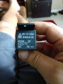
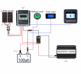
For background though, I’ve basically replicated the wiring setup of this design -
https://www.mobile-solarpower.com/the-minimalist-great-for-small-vans-and-cars.html, that is available on the Mobile Solar Power website to install a system for a small off grid cabin but using a much cheaper PWM solar charge controller (commonly seen on eBay very cheap with black plastic rectangular body and blue face with LCD readout) and using two deep cycle batteries but the solar system at the cabin was over-utilised by some people who stayed in the cabin for a long stay and the LVD feature never activated to protect the batteries and the battery voltage dropped to below 10 Volts.
So, I’m not sure at this point whether the system is such that the LVD has been effectively bypassed due to the way it is wired up and that is a bit of a design flaw or whether the super cheap PVM controller is faulty but that’s why I’m seeking advice here. If the system is wired correctly and such that the LVD is not bypassed then it could be that the cheap controller is faulty and the inbuilt LVD is not working.