Use AJ Madison site to compare pints per watts of dehumidifiers to Energy Star window ACs. https://www.ajmadison.com/cgi-bin/ajmadison/UD501KOJ5.html compared to https://www.lg.com/us/air-conditioners/lg-LW8019ER-window-air-conditioner from 2nd page of https://www.energystar.gov/productfinder/product/certified-room-air-conditioners/results. That LG dehumidifier and LG AC cost about the same. I own that LG AC. It's a bit windy out the hot side to put the entire unit inside a house and use only as a dehumidifier. It can be used as a very efficient window AC while it is dehumidifying. Dehumidifiers can't be used as ACs. I flip my LG around backwards and use it as a heater in the winter. I also own a Midea u-shaped inverter AC. I would definitely buy the Midea to use only as a dehumidifier.


You are using an out of date browser. It may not display this or other websites correctly.
You should upgrade or use an alternative browser.
You should upgrade or use an alternative browser.
WILL... I'm sorry but....
- Thread starter BahamianPrepMan
- Start date
Boondock Saint
Solar Enthusiast
- Joined
- Apr 8, 2021
- Messages
- 662
The DeLongi portable units are fan, AC, heater and dehumidifier AIO, but they still need an external vent.
Rider
Solar Addict
Surprisingly, this dehumdidifier is still going strong (jinx...).Yeah. After going thru a few, I got a cheapo from WallyMart, a TCL. Had lots of features like auto-defrost and a pump to push the water out. It's only been a few months, so we'll see how long it lasts. I also got a 3 year extended warranty.
curiouscarbon
Science Penguin
- Joined
- Jun 29, 2020
- Messages
- 3,025
atmospheric water generation is cool !!!
haha literally because water condenses on cold surfaces…

 memory-alpha.fandom.com
this thread has some info if you’re interested:

 diysolarforum.com
aquaboy device seems legit. good filtration of Air and Water. stainless steel tanks. UV water sanitizer. tried to buy one last year but order was cancelled due to no stock.
cheers and hope everyone got access to good water ?
if you want to do it yourself, ensure that you do the following:
 hackaday.io
haha literally because water condenses on cold surfaces…
Atmospheric condenser
An atmospheric condenser was a device that could extract water from the air. Kamin, a resident of Kataan, suggested building atmospheric condensers to fight the constant drought that was affecting the planet to his community's administrator. Each community would be responsible for its own...
memory-alpha.fandom.com
this thread has some info if you’re interested:
I'm interested in a hiked-in wilderness water collection setup using solar energy
My bestie and I have been trail building in the wilderness for quite a number of years. We have developed this one trail and cleared out a large area of undergrowth on the top of a majestic coastal mountain with an awesome view and call it Red Corn Camp. There is no water supply on the top of a...
diysolarforum.com
aquaboy device seems legit. good filtration of Air and Water. stainless steel tanks. UV water sanitizer. tried to buy one last year but order was cancelled due to no stock.
cheers and hope everyone got access to good water ?
if you want to do it yourself, ensure that you do the following:
- filter the air of particles with HEPA filter
- Food Safe cold surface to condense onto
- pull air up so drips go down
- Stainless Steel pot/tank for collection
- UV sanitizer on water collection tank
- water filtration
- UV sanitizer in holding tank after filter
Smart Dew-Point Water Harvester
750 million people around the world lack access to safe drinking water; approximately one in nine people. One source of clean water is harvesting it directly from the air. Dew point is the temperature at which the water vapor in a sample of air at constant barometric pressure condenses into...
Last edited:
curiouscarbon
Science Penguin
- Joined
- Jun 29, 2020
- Messages
- 3,025
good point about needing to filter Air before condensing water from itYes pulling from air. That is still dirty. There's bajiollions of tons of micro-plastic in the air everywhere, and that micro-plastic also has bacteria and virus, from other continents. Unless water was collected on the filtered side of a collection, then other metals and poisons and airborne funk would be a contamination.
No matter where or how I attempted to collect water, even via humidity, I would boil and filter filter well.
Just because you're not paranoid doesn't mean they aren't out to poison you.
You could use Peltier thermo-electric plates to both contribute to the cooling and heating of a system via both sides at once, but they aren't very efficient.
Peltier is inefficient at full bore 100% as you say, Coefficient of Performance only 0.25-1.0
At 10-25% of max current, peltier element can go up to as high as 3.0 coefficient of performance.
But this also has to do with delta temperature across the hot and cold sides. Some unit have max delta T of 60-70C. So 10% of that is like 6.5C. But at ambient 20-30C you would need 4-5 serial layers of peltier elements to satisfy both constraints to operate efficiently. Such complex, and delicate to keep operating efficiently..
That’s 3.0 thermal Watt moved per 1.0 electrical Watt input, pretty decent. About 10BTU/hr for one watt. Of course there are all sorts of grades of peltier elements and some will just heat up a lot regardless.
Anyways just sharing for fun of study, not arguing that any of this is strictly true. Just another perspective.
curiouscarbon
Science Penguin
- Joined
- Jun 29, 2020
- Messages
- 3,025
if the air where you are has high Relative Humidity >60% then an atmospheric water generator will operate noticeably more efficiently than if it were 20-40% RH ?Maybe I've been under a rock or something, but I didn't even know this was possible. after watching your vid I started digging. I was #Inspired lol. The islands have CRAZY HIGH humidity like ALL the time. I'm thinking that (theoretically) the proficiency of a system like that in the Bahamas (where I live) has just GOT to be super!
Boondock Saint
Solar Enthusiast
- Joined
- Apr 8, 2021
- Messages
- 662
I like the mathematical mindset in the least. My point on the peltier is that given it's inefficiency it's still a two-for.
I can't see it as a total solution but an add-on in a condensation / purifying system.
heat heat heat Heat HEAt HEAT . . . then cool Cool COol COOl COOL down again as vapors pass through a collection cavity.
I can't see it as a total solution but an add-on in a condensation / purifying system.
heat heat heat Heat HEAt HEAT . . . then cool Cool COol COOl COOL down again as vapors pass through a collection cavity.
Boondock Saint
Solar Enthusiast
- Joined
- Apr 8, 2021
- Messages
- 662
I can see a thin cavity with many heatsink fins that are very closely interlaced in order to maximize the surface area in the elongated channels.
As air goes through so many feet of this it is bombarded with electrostatic and UV energy on the heat side. The pre-stage physical filtration at a hepa level would eliminate large non bio particles plus the ionizing and UV bombardment would also cleanse microbes too small for hepa filtration capture. (take THAT you covid biotches!)
The super hot moist air would then be circulated through the same number of linear feet of peltier (other side of plates) before the final condensing unit.
It might be more effective if used in conjunction with or to modify an existing osmotic unit and then required minerals could be re introduced.
Rider
Solar Addict
And..... I jinxed it. Died last week. Fortunately, knowing how often dehumidifiers fail, I bought it with a 3-year warranty. Filed an online claim (Allstate) and we settled for about $15 less than I paid for it back in August of 2019.Surprisingly, this dehumdidifier is still going strong (jinx...).
Rider
Solar Addict
I bought a couple of personal water filters from the local big box store. Filters bacteria, mold, spores like Crypto and micro plastic. Will filter up to 100,000 gallons. There's also tablets available at any camper supply which are very effective, and I have a couple different kinds in my bug out kits. In a pinch, a few drops of chlorine bleach works fine.Yes pulling from air. That is still dirty. There's bajiollions of tons of micro-plastic in the air everywhere, and that micro-plastic also has bacteria and virus, from other continents. Unless water was collected on the filtered side of a collection, then other metals and poisons and airborne funk would be a contamination.
No matter where or how I attempted to collect water, even via humidity, I would boil and filter filter well.
Just because you're not paranoid doesn't mean they aren't out to poison you.
You could use Peltier thermo-electric plates to both contribute to the cooling and heating of a system via both sides at once, but they aren't very efficient.
A solar powered dehumidifier is part of my survival plan.
Bossrox
Solar tinkerer
I'm wondering why anyone would go thru all that trouble, expense & taxing your solar system to collect water, wouldn't funneling rain water into a drum be more cost effective? Either way you still have to purify it but less tedious gathering rain water.
curiouscarbon
Science Penguin
- Joined
- Jun 29, 2020
- Messages
- 3,025
Was sleepy, your sarcasm is unappreciated. More engineering help would be preferable, if I’m to be honest.I like the mathematical mindset in the least. My point on the peltier is that given it's inefficiency it's still a two-for.
I can't see it as a total solution but an add-on in a condensation / purifying system.
heat heat heat Heat HEAt HEAT . . . then cool Cool COol COOl COOL down again as vapors pass through a collection cavity.
Having high temperature high humidity air is what I was trying to refer to. Higher temperature air can hold more water.
Peltier can achieve COP of 3 if this doesn’t make sense or you disagree then it’s just you fighting facts with sarcasm.
Have a great day!
curiouscarbon
Science Penguin
- Joined
- Jun 29, 2020
- Messages
- 3,025
At least in this post you tried..I can see a thin cavity with many heatsink fins that are very closely interlaced in order to maximize the surface area in the elongated channels.
As air goes through so many feet of this it is bombarded with electrostatic and UV energy on the heat side. The pre-stage physical filtration at a hepa level would eliminate large non bio particles plus the ionizing and UV bombardment would also cleanse microbes too small for hepa filtration capture. (take THAT you covid biotches!)
The super hot moist air would then be circulated through the same number of linear feet of peltier (other side of plates) before the final condensing unit.
It might be more effective if used in conjunction with or to modify an existing osmotic unit and then required minerals could be re introduced.
Wait...Was sleepy, your sarcasm is unappreciated. More engineering help would be preferable, if I’m to be honest.
Having high temperature high humidity air is what I was trying to refer to. Higher temperature air can hold more water.
Peltier can achieve COP of 3 if this doesn’t make sense or you disagree then it’s just you fighting facts with sarcasm.
Have a great day!
Peltier can achieve a COP of 3???
everything I have researched on peltier shows it as extremely inefficient...
Can you show the testing of this achievement?
curiouscarbon
Science Penguin
- Joined
- Jun 29, 2020
- Messages
- 3,025
Most people are buying 127 junction peltier squares 40x40mm which are rated for 6 Amperes at 12-15 Volts or About 2 Ohms.
They run ~12V through this 2Ohm resistor and summarily claim that Peltier Is Dead End. They try to achieve DTmax and come up short. They run Umax and say it’s inefficient. They curse the wasted money and move on. With a single layer. Umax.
There are 127 junction peltier squares same size 40x40mm and rated for 15 Ampere at 15.4 Volts. Or about 1 Ohm resistor. I personally prefer these due to less Joule Heating.

When you watch an aspiring engineer attempting to make their Peltier Air Conditioner on a youtube video, this is the efficiency regime that is usually targeted:

Please note the following:

Please note the following:
edit: To clarify that this is going to actually pump a usable amount of heat, adding graph.

Please note:
I hope this has clarified the aforementioned claim regarding Varying Efficiency in Peltier Design
They run ~12V through this 2Ohm resistor and summarily claim that Peltier Is Dead End. They try to achieve DTmax and come up short. They run Umax and say it’s inefficient. They curse the wasted money and move on. With a single layer. Umax.
There are 127 junction peltier squares same size 40x40mm and rated for 15 Ampere at 15.4 Volts. Or about 1 Ohm resistor. I personally prefer these due to less Joule Heating.
When you watch an aspiring engineer attempting to make their Peltier Air Conditioner on a youtube video, this is the efficiency regime that is usually targeted:
Please note the following:
- COP is < 0.7 at all voltages
- DT is > 30 C at all conditions
Please note the following:
- DT is < 40 C for all conditions
- COP is >2 for quite a large space.
- Between DT 0-10 a COP of 4 is achievable.
- Using a drive voltage of 2 Volts instead of Umax or 15.4 Volts is therefore justifiable as a design option.
- By layering devices running at COP 4 the heat gain sandwich advice from people running COP 0.4 will be more easily managed
edit: To clarify that this is going to actually pump a usable amount of heat, adding graph.
Please note:
- Qc refers to Thermal Watt Pumped
- At 2 Volts, DT=0C, Qc = approx 35 W
- At 2 Volts, DT=10C, Qc = approx 10 W
- At start it pumps 35W reducing to 10W pumped at DT=10C
- At COP around 3
- Cascading units operating at COP >> 1 is easier to engineer than at COP << 1
- Target 10C DT per layer if you want COP >= 3
I hope this has clarified the aforementioned claim regarding Varying Efficiency in Peltier Design
Last edited:
Rider
Solar Addict
They each supplement each other. If you look at the western US right now, it's in one of the worst droughts in a very long time, 26% of the areas considered 'exceptional drought'. No rain, no rain barrels being refilled. A dehumidifier solar system can produce water even in a severe drought.I'm wondering why anyone would go thru all that trouble, expense & taxing your solar system to collect water, wouldn't funneling rain water into a drum be more cost effective? Either way you still have to purify it but less tedious gathering rain water.
curiouscarbon
Science Penguin
- Joined
- Jun 29, 2020
- Messages
- 3,025
Atmospheric condenser
An atmospheric condenser was a device that could extract water from the air. Kamin, a resident of Kataan, suggested building atmospheric condensers to fight the constant drought that was affecting the planet to his community's administrator. Each community would be responsible for its own...
memory-alpha.fandom.com
curiouscarbon
Science Penguin
- Joined
- Jun 29, 2020
- Messages
- 3,025
Collected the following:Wait...
Peltier can achieve a COP of 3???
everything I have researched on peltier shows it as extremely inefficient...
Can you show the testing of this achievement?
| Count | Name | URL | usd |
|---|---|---|---|
| 1 | 10pcs peltier element TEC1-12715 | 50 | |
| 2 | 1pcs thermal pad 12.8 W/mK, 85x45x0.5mm | 13 | |
| 1 | 1pcs CPU heatsink 180W TDP 120mm | 65 | |
| 1 | TekPower DC Bench Supply |
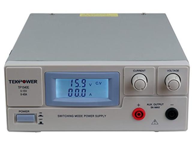
TekPower TP1540E DC Adjustable Switching Power Supply 15V 40A Digital Display (TP1540E) - Newegg.comBuy TekPower TP1540E DC Adjustable Switching Power Supply 15V 40A Digital Display (TP1540E) with fast shipping and top-rated customer service. Once you know, you Newegg!
| was 190 |
| 1 | PC Fan 40x40x20mm | 15 | |
| 1 | Non-Contact Infrared Thermometer | 30 |
Important Note: Emissivity was not corrected for in this method. Need retesting with thermocouples to 16/24-bit ADC.
Procedure:
Connect positive of first element to negative of second element. Connect positive of second element to negative of third element.
Connect negative of first element to DC Bench Supply Negative. Connect positive of third element to DC Bench Supply Positive.
I set up a separate 12V supply for the PC fan. Any wall wart 12V should be fine.
Apply the thermal pads between the face of the heat sink and the successive peltier elements.
Sequence: heat sink -> pad -> peltier 1 -> pad -> peltier 2 -> pad -> peltier 3 -> air

Adjust Bench Supply Current up. Adjust Supply Voltage all way down. Turn on power supply with 3 series TEC1-12715 connected as described above. Confirm 0V 0A on supply.
Adjust voltage to 0.1V and wait 20 seconds for temperature to stabilize, then record heat pipe/fin temperature and cold face temperature using non-contact thermometer, ensuring to consistently and accurately point the IR sensor at the point of interest.
Repeat for 0.1, 0.2.. 1.0, 1.1, 1.2.. 2.0, 2.5, 3.0, 3.5, 4.0, 4.5, 5.0, 5.5, 6.0, 6.5, 7.0, 7.5 Volts. Note amps at each Volt Step. Wait for temperature to equalize at each stage. Ensure accurate aiming of thermometer. Try my best because the bench only has tenths precision.
Expectation: ~2.0V per module ( 3 modules in series * 2.0 per module = 6.0 V for string ) to be target for operation as per earlier post. Approximate voltage, need actual data sheet or better characterization.
Result: 2.0V per module resulted in heat pipe T=31.0°C and cold side T=-1.9°C for a dT = 32.9°C. 6.0V * 1.7A = ~10.2W.

Yes, deciWatts. 10 dW = 1W.

This legend should say power fit, not linear fit or polynomial fit. My bad. Will fix in an update.

Please forgive me for the poor formatting of the graphs, and likely an error of unit labels that I didn't notice. Used apple spreadsheet software which has limited control over the small details of graph format.
Curious what other people have to think about this. This represents a collection of random observations, likely with large oversights in design. Would kindly request respectful feedback that addresses these specific observations. Edited spreadsheet to show C not ambiguous "T".
After thinking a little about the topic of DC Regulation Efficiency, Another random observation..
Code:
> (3.0 V * 3 cells) / 5 layer
1.8 V / layer
> (3.4 V * 3 cells) / 5 layer
2.04 V / layer
> (3.65 V * 3 cells) / 5 layer
2.19 V / layer
TL;DR ran 10W @ 6 V through three peltier TEC1-12715 module in series and water condenses on the cold face when i breathe on it (quicker) or point a small fan at it (slower). hot side = 31°C, cold side = -1.9°C, dT = 32.9°C, RH ambient = 36%RH
Still, at the end of this post, I don't have a clear COP to give you @Supervstech. Hopefully this is still fruitful for discussion. If anyone notices a flaw in the described methodology, please bring it up so that it can be addressed ?
Last edited:
curiouscarbon
Science Penguin
- Joined
- Jun 29, 2020
- Messages
- 3,025
Recorded 30 minutes of video of the cold side with 6V 1.7A (10.2W) applied. The tiny fan pointed at the cold side. Ambient 26-27°C. Hot side up to 34-38°C (heatsink had no fan) humidity ambient RH 37% Cold side ~9C? Condensation occurred with 10W input to peltier and 0.6W to PC fan which is supposed to be good for about 5 CFM.
Will upload a fast forward version when I can compress it down from 15GB. Here are my notes from scrubbing through it:
ok.. counted precisely six droplets that fell off the peltier square. 14 minutes to first droplet. about 19 minutes from then until six droplets made.
that's 3.12 minutes per droplet or 0.32 droplets per minute. (after first droplet falls) 10.2 W for 32.4 minutes = 10.2W*0.541hr = ~5.52 Wh.
0.92 Wh/ droplet? 1.08 droplets / Wh?
quora says 0.05 mL / droplet.. 5e-5 L / droplet
20000 droplets to get one liter of water...
18.4 kWh / liter
pretty mediocre efficiency with this configuration. it generates water in 37%RH 27°C air though at 10W.
some highlights..
T = 0:00

T=3m

T=5m

T=10m

T=13m46s drop fall

T=17m21s drop fall

T=32m29s final drop fall, test done (how many droplets in 30m? 6.)

Will upload a fast forward version when I can compress it down from 15GB. Here are my notes from scrubbing through it:
Code:
 0:00 power applied 6V 1.7A
 1:34 shimmer of condensation begins
 2:00 visible layer of condensation forming
 5:00 droplets start to combine and become larger
10:00 droplet size peaks and dripping cascade begins
12:00 water has begun to accumulate along bottom edge
13:45  first droplet falls off peltier
17:21 second droplet falls
20:16  third droplet falls
24:18 fourth droplet falls
28:30  fifth droplet falls
32:29  sixth droplet falls
33:00 concluded test
ok.. counted precisely six droplets that fell off the peltier square. 14 minutes to first droplet. about 19 minutes from then until six droplets made.
that's 3.12 minutes per droplet or 0.32 droplets per minute. (after first droplet falls) 10.2 W for 32.4 minutes = 10.2W*0.541hr = ~5.52 Wh.
0.92 Wh/ droplet? 1.08 droplets / Wh?
quora says 0.05 mL / droplet.. 5e-5 L / droplet
20000 droplets to get one liter of water...
18.4 kWh / liter
pretty mediocre efficiency with this configuration. it generates water in 37%RH 27°C air though at 10W.
some highlights..
T = 0:00
T=3m
T=5m
T=10m
T=13m46s drop fall
T=17m21s drop fall
T=32m29s final drop fall, test done (how many droplets in 30m? 6.)
Last edited:
svetz
Works in theory! Practice? That's something else
So 33 minutes and 5.5 Wh for 6 drops at 37% RH with a fan blowing ambient 37°C air on the condenser plate? Did that include the power for the fan? If you take the fan out do you see the same results of 6 drops? At 75708.2 drops per gallon, that would be ~70 kWh/gallon? What was the temperature of the cold plate? Ah, -1.9°C. From the table to the right, looks like for that RH you needed around 12°C to get condensation. So, some savings there. Makes me wonder how much yield might increase if there was more surface area on the cold side. |

|
curiouscarbon
Science Penguin
- Joined
- Jun 29, 2020
- Messages
- 3,025
indeed i did not include the 0.5W fan in final figure as i ought to have.
18.4 kWh / liter is what i calculated excluding fan power, which works out to ~70 kWh/gal.
with fan more like 5.9-6.0 Wh for 33min.
maybe call it a solid 75 kWh/gallon for this level of sophistication
i can get one drop in about a minute or two if i exhale air directly onto it with pursed lips. and i can get lightheaded, ha
next steps… sensors and mosfets!
curiouscarbon
Science Penguin
- Joined
- Jun 29, 2020
- Messages
- 3,025
Ok now 7 are stacked with thermal pads between each layer. Series connected.
Ran 7.5 V @ ~1.0 A through seven TEC1-12715 in series, stacked, thermal pads, etc.. ~1V/module.
Recorded at steady state with seek thermal cam

edit: punched in dewpoint formula to grapher, should be easy to combine with a humidity sensor that reports %RH and °C.

edit^2:


edit^3: add gif of startup from off state to show temperature gradient forming (this one is without the copper plate)

if i exhale onto the copper surface directly, condensation forms readily.
Ran 7.5 V @ ~1.0 A through seven TEC1-12715 in series, stacked, thermal pads, etc.. ~1V/module.
Recorded at steady state with seek thermal cam
edit: punched in dewpoint formula to grapher, should be easy to combine with a humidity sensor that reports %RH and °C.
edit^2:
placed a 10x5x0.3cm copper plate on top of cold side and placed a bit of gaff tape while dry to provide high emissivity measurement target for non contact infrared thermometer. ensured there was a layer of water between cold side and copper plate.Makes me wonder how much yield might increase if there was more surface area on the cold side.
edit^3: add gif of startup from off state to show temperature gradient forming (this one is without the copper plate)
if i exhale onto the copper surface directly, condensation forms readily.
Last edited:
jasonhc73
Cat herder, and dog toy tosser.
I put a PVC connector on my AC condensate drip. Then a regular garden hose, then a drip hose.You would be SET. So much free water. Its so easy! haha


At the end of summer it looks like this:
curiouscarbon
Science Penguin
- Joined
- Jun 29, 2020
- Messages
- 3,025
Nice!I put a PVC connector on my AC condensate drip. Then a regular garden hose, then a drip hose.
View attachment 53879 View attachment 53878
At the end of summer it looks like this:
Any issues with clogging? Great work! ?
curiouscarbon
Science Penguin
- Joined
- Jun 29, 2020
- Messages
- 3,025
The best numbers I could find online were 250-310Wh/Liter of H20 from air. That's the number to match or beat ")
edit: looking at this: https://en.wikipedia.org/wiki/Atmospheric_water_generator#Modern_technologies not saying it's real but that's the claim to beat on the brightest outlook

 newatlas.com
edit: looking at this: https://en.wikipedia.org/wiki/Atmospheric_water_generator#Modern_technologies not saying it's real but that's the claim to beat on the brightest outlook
Watergen tech produces clean drinking water in your car
If you get thirsty while driving, you may soon be able to drink water generated by a system that's built right into your car. The technology could reportedly also provide water for the onsite rinsing of dirty work equipment, or for keeping automotive sensors and engine parts clean.
newatlas.com
Last edited:
Similar threads
- Replies
- 8
- Views
- 329
- Replies
- 9
- Views
- 318
- Replies
- 0
- Views
- 325
- Replies
- 11
- Views
- 425