diy solar

diy solar

Wire ways and wiring?

wrench 87

New Member
Joined
Feb 19, 2022
Messages
59
Location
Seekonk, Ma
I just wanted to know before I start wiring my project if I should be using grounding bushings and where.
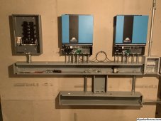
Any information or advice would be helpful. I have a. Lot of conduit stubs and a few chase nipples, the bottom race way is for the batt cables one junction box is for abb breaker and the hinged box for pv breakers.BF911ABD-79E1-49BA-B0F8-C11790138F7C.jpeg
 
They are required if the connected equipment is not listed as suitable for bonding. So pretty much all metal conduit, enclosures and fittings are listed. The other case is if the conduit is serving as the EGC. In that case I think both ends require a bonding bushing.
 
You don't need bonding bushings for anything in the picture. As long as you install EGC's in everything. I would recommend plastic bushings everywhere. (May be required in your area) Unless the fittings have plastic throats already.
 
I have all the plastic bushings, so the box withe the hinged door has a welded stud on the door and inside box, the junction box has a raised boss for a ground screw. can i just add a ground bar in each of the wire ways then connect them all together and terminate in the electrical box on the ground bar? if so what size wire could I use 10awg or 8 awg.
 
if so what size wire could I use 10awg or 8 awg.
Completely dependent on your maximum current circuit. What is it?

(And then go into the NEC EGC sizing table. IIRC you are good to 100A with #8, and #6 is good to any reasonable current at home)

I’m not sure what you are trying to save though. I guess you can land the EGC for every conduit going into wireway right on ground bar. And then bond through wireway past that. That will somewhat reduce the ratnest of wires.

But then why use ground bar instead of bonding bushing? I guess it is more solid to use a ground bar (either is up to code).

And if bonding through wireway, why the question about the EGC size? Unless you were asking about the EGC in each conduit entering the wireway

Might want to run the DC EGC separately in case grounding requirement changes ?
 
Wouldn’t it be better to just run insulated EGC between all the components panel/inverters/breaker box?
land the EGC for every conduit going into wireway right on ground bar. And then bond through wireway past that.
Seems excessive going through every single piece of conduit. That’s 12 EGC runs just for the two inverters.
 
Seems excessive going through every single piece of conduit. That’s 12 EGC runs just for the two inverters.
I don’t think it would be. I meant at most one EGC per conduit. Instead of relying just on the conduit to bond.

So #8 or #10 for each inverter to the wireway.

Inverter might have 2-3 circuits going out different conduits. If bonding through the wireway there would be no need to directly connect a EGC to those conduits.

It is mathematically the lowest number of EGC you need in each conduit (well it could be zero if bonding through conduit, not sure if inverters are listed for that given they have ground terminals and sus chassis). It might not be the fastest way to do it
 
I have all the plastic bushings, so the box withe the hinged door has a welded stud on the door and inside box, the junction box has a raised boss for a ground screw. can i just add a ground bar in each of the wire ways then connect them all together and terminate in the electrical box on the ground bar? if so what size wire could I use 10awg or 8 awg.
I would put a ground bar in each wire way. This will cut down on the amount of EGC's running every which way. This way you only need one EGC from each piece of equipment to the wire way. And a EGC between the two wire ways running through the junction box. Bonding the junction box as it passes through.
 
I dont want to use the grounding bushings I would have to use 30 of them counting the 2 stubs where the battery cables would enter, I would like to use 2 grounding bars in the race ways and take advantage of the studs in the hinged door junction box and the raised boss in the other junction box.
I have a 60 amp main breaker to feed my electrical box, I will just use a couple of quad outlets and a 240v outlet for now so I will have to install its own ground rod ? what size ground cable should i use to connect all the boxes together.
 
Minimum size EGC for 60a is a #10. You can go larger, but not smaller.
If you have an existing electrical system. You already have an established grounding system. All new equipment should be connected to the existing grounding system. (One grounding system for everything)
 
This is going to be its own system for now , so it will not be tied into my main panel. I would like to possibly run a mini split with heat pump and a dehumidifier in my basement and just have some outlets to plug into and possibly use to charge my tesla model y. I like to learn new things so just learning as I go. This is where I get confused if I leave the bonding screw out and run a ground back to my main panel would that be ok, or should I just leave this as a seperate source of power and bond the panel and use its own ground rod?
 
This is where I get confused if I leave the bonding screw out and run a ground back to my main panel would that be ok, or should I just leave this as a seperate source of power and bond the panel and use its own ground rod?
Neither would be correct.
If it's a separate system. You will need a N/G bond. If it's not created by the inverter, you will need to create it yourself.
Since you have an existing grounding system. The new equipment should be connected to it. There should only every be one grounding system. Do not add any additional auxiliary ground rods. The existing grounding system should already have the connection to earth.
 
Back
Top