diy solar

diy solar

Wiring 16 cells into 24v battery???

Short Answer: NO

Longer answer,
When the batteries are full, the solar charge controller effectively 'disconnects' the panels... letting them drift to their Voc (Open Circuit Voltage).
It turns out that it takes very little light for a panel to generate the full open circuit voltage. People have reported seeing Voc at dusk after the sun is below the horizon. Consequently, even if the panels are at a terrible angle, they are likely to experience the full open circuit voltage.

Very instructional, you should be a "Solar Professor" at some school. LOL

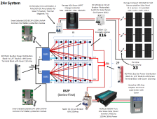
I've updated my design, any thoughts on the breaks I chose. Other than needing to find out about a bi-directional one on the output side of the SCC. I want this to be perfect for future users reference.
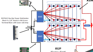
24v.complete.system.png
 
If you don't mind my asking, why didn't you?
Your answer may help someone else.
Honestly, I guess I did, but I started with a kit for Renogy.com 4-years ago, and there are a lot of things they don't do that they probably should, like a BMS. I have been running my 40am Rover with 8 100watt panels for 3 years now. I have a bank of currently 8 3.2v Lifopo4 batteries, and that 3000w inverter. Everything has been working, but clearly I set it up wrong, and I see that now.
 
* There need to be fuses (or breakers) on each 3S string of panels.
* The breaker on the output of the charge controller should be larger. If the controller can produce 40A, the breaker should be 1.25x40A=50A.
* The breaker on the inverter needs to be larger. (I calculate 175A).
* The wire sizes need to be chosen to handle the current of the associated breaker
* I like to put a fuse between the batteries and the rest of the system.
* I would add a shunt/battery monitor so I can see the state of charge (SOC) of the batteries. SOC is the most valuable bit of data in the day-to-day operation of a system.
 
Backing up a bit, there is an "opportunity" to arrange your 2P8S batteries in good and bad ways.

We've seen people match the 2P pairs with equal capacity/strength cells and lots of random pairings.

Ideally, you want each 2P pair to be equal combined capacity/strength to be the same within each battery.

It takes a bit of effort and capacity testing is the best way, to get your battery configured properly.

I have not gone thru building 2 batteries with 32 cells which would allow even more flexibility (possible combinations!) in creating 2 batteries, each with 8 equal pairs of 2. Far more important to have the cell pairs equal to each other within the battery than to make the batteries equal (but thats a good secondary thought).

To form a 2P8S battery from 16 cells, you'd create the best possible battery by pairing the strongest with the weakest. Pair the second strongest with the second weakest, pair the third strongest with the third weakest....

What does that do as far as the wiring of the BMS though? My understanding is a BMS only likes batteries in series...
 
It has to do with which cells you put in pairs when making your batteries, BEFORE you wire the BMS.

If you randomly pair cells when making your 2P8S batteries, you can be lucky or unlucky in how balanced your battery will be. To build a better battery, creating 2P pairs equal to the other pairs in each battery is what i believe to be the best option (only option?).

These are the cell pairs. You mention 8S battery with 2P pairs but your pic is of a 2P4S battery (8 cells, 4 pairs). Confused now...

View attachment 131485
Now I am confused. His latest diagram shows 8S batteries arranged in 2P (8S2P). Why are we discussing 2P8S?
 
Now I am confused. His latest diagram shows 8S batteries arranged in 2P (8S2P). Why are we discussing 2P8S?
Oh crap, i saw it wrong on this little screen, sorry.
I saw the title of the thread (from a different person i realize now) with 32 cells and got completely jumbled.

Sorry, i will delete and clean up posts as well as i can. Sorry to the OP for trampling and sorry to McLovin for getting this so horribly wrong! Thanks FilterGuy for setting me straight!
 
* There need to be fuses (or breakers) on each 3S string of panels. = https://www.amazon.com/gp/product/B08L56RDNP/ref=ox_sc_act_image_1?smid=AWA4NAV5T95KM&th=1

* The breaker on the output of the charge controller should be larger. If the controller can produce 40A, the breaker should be 1.25x40A=50A. = https://www.amazon.com/Miniature-Ci...74678407&sprefix=50am+dc+,aps,104&sr=8-5&th=1

* The breaker on the inverter needs to be larger. (I calculate 175A). = https://signaturesolar.com/nader-dc...eF4P5q2pknaqJ-C2HqdxdOXB7lL67idblcCZ9Xl7b4fyA

* The wire sizes need to be chosen to handle the current of the associated breaker = I am being mindful about that. Especially between the inverter and the battery bank. 4awg

* I like to put a fuse between the batteries and the rest of the system. = like a 50amp ANL fuse? Where would it go? On the positive line between the battery and the positive busbar?

* I would add a shunt/battery monitor so I can see the state of charge (SOC) of the batteries. SOC is the most valuable bit of data in the day-to-day operation of a system. That seems to be a feature of the SCC, it does show Volts and SOC.
 
Oh crap, i saw it wrong on this little screen, sorry.
I saw the title of the thread (from a different person i realize now) with 32 cells and got completely jumbled.

Sorry, i will delete and clean up posts as well as i can. Sorry to the OP for trampling and sorry to McLovin for getting this so horribly wrong! Thanks FilterGuy for setting me straight!

I swear I think you too are family. LOL
 
Two things caught my eye.
1) Check the voltage limits on the charge controller input and make sure it can handle the voltage from 10 panels in series. Note: Be sure to adjust for cold temp when calculating the array voltage.

2) Make sure the breaker on the output side of the charge controller is bidirectional.

Why would I want a "bidirectional" DC breaker on the output side of the charge controller? Due to this:

1674680076976.png
 
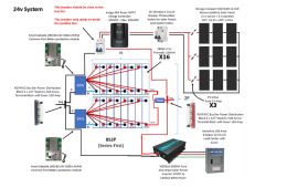
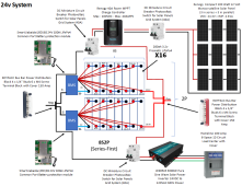
Ok, here is another updated plan for my system based on all the recommendations, with the exception of the question about the fuse to isolate the battery bank...
24v.complete.system.png
 
Your busbars are nickel plated brass, suggest you want copper busbars rated to at least 250 amps.
Each battery should have a class t fuse.
Since you don't indicate the wire sizes we can't verify your over-current protection sizing.
 
* The breaker on the output of the charge controller should be larger. If the controller can produce 40A, the breaker should be 1.25x40A=50A. = https://www.amazon.com/Miniature-Ci...74678407&sprefix=50am+dc+,aps,104&sr=8-5&th=1

I can't tell if that is directional or bidirectional, but the + and - sign makes me think it is.
Why would I want a "bidirectional" DC breaker on the output side of the charge controller? Due to this:

View attachment 131486

First: The breaker on the output of the charge controller is there to protect current from the battery from causing a problem. (Not current from the charge controller) Consequently, the breaker should be as close to the busbar as possible.


With DC breakers, they must have special accommodations to extinguish an arc that might form when the breaker opens. A directional DC breaker only does this when the current is flowing in the correct direction. If the breaker is manually opened when the current is flowing in the wrong direction, an internal arc can form and continue.... causing a fire. Furthermore, a directional breaker will not open in an over-current situation if the current is going in the wrong direction.

So, if you use a directional breaker and wire it to trip on current from the battery, it could arc and catch fire if you open it manually while the current is flowing from the charge controller. If you wire it the opposite way, it won't trip if there is a short between the breaker and the charge controller.

I can not tell if the breaker you linked to is directional or not. However, the + and - on the terminals makes me think it is directional.
 
I can't tell if that is directional or bidirectional, but the + and - sign makes me think it is.


First: The breaker on the output of the charge controller is there to protect current from the battery from causing a problem. (Not current from the charge controller) Consequently, the breaker should be as close to the busbar as possible.


With DC breakers, they must have special accommodations to extinguish an arc that might form when the breaker opens. A directional DC breaker only does this when the current is flowing in the correct direction. If the breaker is manually opened when the current is flowing in the wrong direction, an internal arc can form and continue.... causing a fire. Furthermore, a directional breaker will not open in an over-current situation if the current is going in the wrong direction.

So, if you use a directional breaker and wire it to trip on current from the battery, it could arc and catch fire if you open it manually while the current is flowing from the charge controller. If you wire it the opposite way, it won't trip if there is a short between the breaker and the charge controller.

I can not tell if the breaker you linked to is directional or not. However, the + and - on the terminals makes me think it is directional.

When you say:
However, the + and - on the terminals makes me think it is directional.
... are you saying you think I have a correct breaker then? Sorry, got a little confused, I re-read it three times and was just making sure you weren't using bidirectional and directional interchangeably...
 
* The breaker on the inverter needs to be larger. (I calculate 175A). = https://signaturesolar.com/nader-dc...eF4P5q2pknaqJ-C2HqdxdOXB7lL67idblcCZ9Xl7b4fyA
That should work.

* I like to put a fuse between the batteries and the rest of the system. = like a 50amp ANL fuse? Where would it go? On the positive line between the battery and the positive busbar?
Each battery should have a class t fuse.
Fusing on batteries gets complicated.
The BMS has short circuit protection that will *almost* always pop before a fuse or breaker pops. However ,the BMS short circuit protection relies on a lot of complex circuits to operate and therefore a lot of people do not consider it reliable and additional protection is needed.

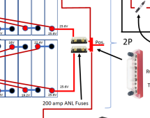
The additional protection can be added at the output of each battery or can be added after/at the busbar. In server rack batteries, most people add it after the busbar and that is what I typically do. However, if the wiring between the battery and the busbar is long and/or exposed, there should be fuses on each battery. (I will assume you will put it at/after the busbar) perhaps something like this:
1674683369985.png


The size of the fuse (Or breaker) needs to be large enough to handle the max continuous current. That will be current to the inverter.... so the same size as the breaker you have selected for the inverter. However, if you add the protection at the battery, you don't really need another one for the breaker.

1674684244481.png
The next logical question is "can it be a breaker instead of a fuse". The answer is yes.... but....
1) I tend to stay with fuses when the current gets above 100A and certainly at 200A.
2) If a breaker is used, it needs to have a very high Interrupt capability (This is NOT the same as the trip value). In a short circuit situation, the current from LifePO4 batteries will go extremely high long before the breaker opens the circuit. That means the breaker has to interrupt this very high current.
* Most people on the forum say there should be a class-T fuse with an interrupt rating of 20KA.
* The spec sheet of your breaker indicates it has a 10KA interrupt capability but the way it is wired it has two in parallel. I don't know if you can call that a total of 20KA.
* Victron is an excelent company and their sample designs use fuses with much lower interrupt capability.
 
That should work.


Fusing on batteries gets complicated.
The BMS has short circuit protection that will *almost* always pop before a fuse or breaker pops. However ,the BMS short circuit protection relies on a lot of complex circuits to operate and therefore a lot of people do not consider it reliable and additional protection is needed.

The additional protection can be added at the output of each battery or can be added after/at the busbar. In server rack batteries, most people add it after the busbar and that is what I typically do. However, if the wiring between the battery and the busbar is long and/or exposed, there should be fuses on each battery. (I will assume you will put it at/after the busbar) perhaps something like this:
View attachment 131493


The size of the fuse (Or breaker) needs to be large enough to handle the max continuous current. That will be current to the inverter.... so the same size as the breaker you have selected for the inverter. However, if you add the protection at the battery, you don't really need another one for the breaker.

View attachment 131494
The next logical question is "can it be a breaker instead of a fuse". The answer is yes.... but....
1) I tend to stay with fuses when the current gets above 100A and certainly at 200A.
2) If a breaker is used, it needs to have a very high Interrupt capability (This is NOT the same as the trip value). In a short circuit situation, the current from LifePO4 batteries will go extremely high long before the breaker opens the circuit. That means the breaker has to interrupt this very high current.
* Most people on the forum say there should be a class-T fuse with an interrupt rating of 20KA.
* The spec sheet of your breaker indicates it has a 10KA interrupt capability but the way it is wired it has two in parallel. I don't know if you can call that a total of 20KA.
* Victron is an excelent company and their sample designs use fuses with much lower interrupt capability.

So I'm thinking this addition:

1674686227233.png
 
... are you saying you think I have a correct breaker then? Sorry, got a little confused, I re-read it three times and was just making sure you weren't using bidirectional and directional interchangeably...
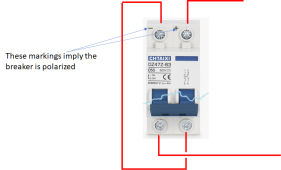
You need a bidirectional or non-polarized breaker. The markings make me thing this is a directional or polarized breaker.

However, all is not lost with this breaker. For this function, only the positive line needs a breaker and that opens up the possibility of using a trick.

1674686025998.png

If the breaker is not polarized, it will open the circuit without a problem.... in fact it is double protected.

If the breaker is polarized, no matter wich way the current is flowing, one side of the two breakers will have the current flowing in the correct direction. This means when the breaker is opened manually or due to over-current, one side of the pair will be able to suppress the arc and that will stop the arc in the other side as well.
 
Back
Top