You are using an out of date browser. It may not display this or other websites correctly.
You should upgrade or use an alternative browser.
You should upgrade or use an alternative browser.
Wiring Diagram: How did I do?
- Thread starter gcp
- Start date
gcp
Going nomadic.
- Joined
- Sep 1, 2021
- Messages
- 49
That's making sense. So I would actually keep a separate battery on the camper for the running gear because there's a breakaway safety switch that needs to be powered in the event of a major failure.My suggestion is to isolate the running gear including e-breaks and tow cable and leave it as a separate system.
A dc2dc charger is going to draw way more current than that tow cable can deliver anyway.
My concern with running a tow cable and a high current dc2dc in parallel is if the high current negative failed the tow cable negative would likely melt or start on fire.
I guess you could fuse both positive and negative but I have not thought this through so I can't recommend it.
Anybody else want to weigh in here?
@RF_Burns I bet you have some wisdom on this.
I had imagined only using the DC-to-DC charger when at a campsite and disconnected from tow vehicle, but actually now that you mention it, it would be nice to be able to use it while driving too. Perhaps putting a circuit breaker on both +/- wires is the thing to do. Appreciate any @RF_Burns can offer! Thank you!
Oh these are perfect, thank you. Makes more sense than combining multiple Victron distro boxes.These are the busbars I used in my setup.
For the negative side I just put 7 zcase fuses underneath the busbar.
Not sure if its supported but I use both mrbf and zcase fuses with these.
Gives more options for price and capacity.
Even with the 7 fuses underneath the negative busbar its a cost effective solution.
John Frum
Tell me your problems
- Joined
- Nov 30, 2019
- Messages
- 15,233
Yep a small lead acid battery should be fine.That's making sense. So I would actually keep a separate battery on the camper for the running gear because there's a breakaway safety switch that needs to be powered in the event of a major failure.
Something isn't adding up here.I had imagined only using the DC-to-DC charger when at a campsite and disconnected from tow vehicle, but actually now that you mention it, it would be nice to be able to use it while driving too.
Where will the dc to dc charger get its power if not from the tow vehicle battery/alternator?
I always try to design human error out of the system.Perhaps putting a circuit breaker on both +/- wires is the thing to do. Appreciate any @RF_Burns can offer! Thank you!
John Frum
Tell me your problems
- Joined
- Nov 30, 2019
- Messages
- 15,233
I've been thinking more about the tow cable and high current dc charger combination.
The 2 concerns I have are...
1. Melting the return wire in the tow cable.
2. Causing a ground loop.
I would want the trailer to be tow-able by any tow vehicle equipped with the standard 7 pin tow cable.
That means the trailer side of the tow cable(interface) should not be made incompatible.
I would also want my tow vehicle to be able to tow other trailers equipped with the standard interface.
That means the vehicle side of the tow cable(interface) should not be made incompatible.
I'm starting to think about a relay and fuse but that just makes more things to go wrong.
@RF_Burns probably has some good insights on this.
gcp
Going nomadic.
- Joined
- Sep 1, 2021
- Messages
- 49
Sorry, I didn't explain that clearly. It would be coming from the tow vehicle battery/alternator at the campsite, but the 7-way-connector wouldn't be connected, so there wouldn't be a return path.Something isn't adding up here.
Where will the dc to dc charger get its power if not from the tow vehicle battery/alternator?
What about rendering the return path in the tow cable inoperative so that the high current cable is the only return path?
I think you're right. I'm trying to learn more about how tow systems work to see how that can work. See new diagram below that shows what I know so far.My suggestion is to isolate the running gear including e-breaks and tow cable and leave it as a separate system.
Love this. Yes, 100% agree.I would want the trailer to be tow-able by any tow vehicle equipped with the standard 7 pin tow cable.
That means the trailer side of the tow cable(interface) should not be made incompatible.
I would also want my tow vehicle to be able to tow other trailers equipped with the standard interface.
That means the vehicle side of the tow cable(interface) should not be made incompatible.
I'm starting to think about a relay and fuse but that just makes more things to go wrong.
@RF_Burns probably has some good insights on this.
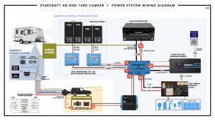
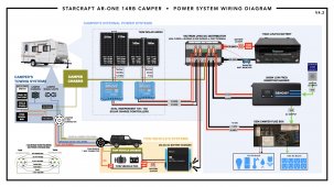
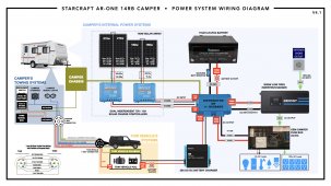
Here's version 4 of the wiring diagram. It now includes the tow vehicle's systems and the camper's towing systems. There are some ???s to resolve in the camper's towing system. Ran out of time to remove the distributor to replace with fused busbars, will do that in the next version of the diagram.

Attachments
John Frum
Tell me your problems
- Joined
- Nov 30, 2019
- Messages
- 15,233
Its a bad idea to run a dc2dc charger off an idling tow vehicle.Sorry, I didn't explain that clearly. It would be coming from the tow vehicle battery/alternator at the campsite, but the 7-way-connector wouldn't be connected, so there wouldn't be a return path.
The alternator will get hot and possibly burn out.
John Frum
Tell me your problems
- Joined
- Nov 30, 2019
- Messages
- 15,233
I see that it is only a 20 amp charger.
You might get away with power the tow cable via the dc2dc charger.
Probably won't get a whole lot of charge as the voltage drop will be severe but it will avoid my 2 big concerns.
The next problem is your turn breaks and signals not working because the dc2dc charger disconnects for a variety of reasons.
gcp
Going nomadic.
- Joined
- Sep 1, 2021
- Messages
- 49
Tow cable gets its power directly from the tow vehicle's power system. Works without the DC-to-DC battery charger. I would run a separate wire for DC-to-DC charger from tow vehicle to camper. And I might get a higher camp DC-to-DC battery charger if I modify my tow vehicle to idle at a higher rate. Manufacturer had an option for triggering the vehicle to activate "extended idle" for powering more devices while stationary (i.e. police car equipment).I see that it is only a 20 amp charger.
You might get away with power the tow cable via the dc2dc charger.
Probably won't get a whole lot of charge as the voltage drop will be severe but it will avoid my 2 big concerns.
The next problem is your turn breaks and signals not working because the dc2dc charger disconnects for a variety of reasons.
gcp
Going nomadic.
- Joined
- Sep 1, 2021
- Messages
- 49
Thank you! Fixed that one in the latest diagram above. Is that the only ground I need to run for that system since everything is connected to the lynx (or busbar if I go that route).Its looks like you have a ground wire bypassing your shunt.
From memory there is a dedicated ground position on the lynx.
John Frum
Tell me your problems
- Joined
- Nov 30, 2019
- Messages
- 15,233
Ok I

I don't know about the pv side of things but for the core system that one bond to chassis in all that is needed.
I think the diagram is good.
Its been fun working on this with you.
Ok just got back from a workout and now the drawing makes much more senseThank you! Fixed that one in the latest diagram above. Is that the only ground I need to run for that system since everything is connected to the lynx (or busbar if I go that route).
I don't know about the pv side of things but for the core system that one bond to chassis in all that is needed.
I think the diagram is good.
Its been fun working on this with you.
gcp
Going nomadic.
- Joined
- Sep 1, 2021
- Messages
- 49
Good! Glad to hear it. It's been a pleasure working with you on this too! I've learned a lot. Thank you so much for your patience and generosity.Ok just got back from a workout and now the drawing makes much more sense
I don't know about the pv side of things but for the core system that one bond to chassis in all that is needed.
I think the diagram is good.
Its been fun working on this with you.
Round trip journey should be approx 30-40ft.What is the estimated round trip length for the wires from the starter battery to the dc2dc charger and back?
Okay, this feels like a final-ish diagram especially now that it has your blessing. I still have some wire gauges to calculate and odds and ends to fill in - easy stuff. All the questions and uncertainties that were holding me up are gone. Thank you so much!
Studying some other wiring diagrams, it looks like I can connect the SCCs to the same terminals on the bus bars, so I'm using the Lynx Distro bus bars for this. Just enough room for everything this way.

Attachments
John Frum
Tell me your problems
- Joined
- Nov 30, 2019
- Messages
- 15,233
25 amps over 40 feet at 12 volts requires 4 awg for < 3% voltage drop.
 baymarinesupply.com
These are good high current connectors.
Interactive Wire Size Calculator
Battery Chargers, Inverters, Solar Components, and Wiring Supplies for Boats, RVs, and Off-Grid Applications.
These are good high current connectors.
RF_Burns
New Member
The DC-DC charger will compensate for the voltage drop from the vehicle to the charger input. The voltage drop between the DC-DC charger to the battery must be kept low as possible, so keep the charger as close as possible to the LiFePO4 battery. I don't have the specs for the Renogy unit, but I think it will go down to about 11V input. Just remember as the voltage drops at the input to the charger, the current increases to compensate, causing a further voltage drop to the input.
gcp
Going nomadic.
- Joined
- Sep 1, 2021
- Messages
- 49
Hey that's a great tip, thank you. I'll put the charger in the camper instead of the tow vehicle to minimize the drop from charger to battery. And I've decided to go with Victron 12/12-30amp instead of the Renogy. The more familiar I've become with how these electrical systems work, the more appreciation I've developed for Victron.The DC-DC charger will compensate for the voltage drop from the vehicle to the charger input. The voltage drop between the DC-DC charger to the battery must be kept low as possible, so keep the charger as close as possible to the LiFePO4 battery. I don't have the specs for the Renogy unit, but I think it will go down to about 11V input. Just remember as the voltage drops at the input to the charger, the current increases to compensate, causing a further voltage drop to the input.
Similar threads
- Replies
- 2
- Views
- 176
- Replies
- 17
- Views
- 460


