diy solar

diy solar

Wiring inverter from charger wires?

JeremyS

New Member
Joined
Sep 27, 2020
Messages
15
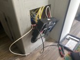
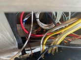
So I'm thinking of wiring a 1000w inverter from the wires from the charger. (splicing into he positive to the actual panel, and neg on the bus bar) Reason being this seems to be the easiest and cheapest way, at least in my head at the moment. Plan is to switch off the charger at breaker when I want to use the inverter, so all outlets will have power, just for small fans, tv etc.....
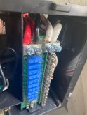
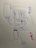
Right now I have a wire from the panel charger input and one from the bus bar, and get 12v power whether breaker from charger is on or off, so my plan is to go from those two wires into inverter, then from inverter to its own 15 or 20amp breaker, so I'll have a 3 step process to enable the system, 1 flip charger breaker off, 2 flip inverter breaker on, 3 power on inverter, I think w/ that many steps it would be difficult to have them all powered on at the same time.
Does this make sense? Am I missing something? I know there are more sure proof ways w/ switch boxes etc, but this just makes pretty good sense to me at the moment
 
I am having a hard time envisioning what you mean. Can you make a sketch?

One comment about “splicing in”...ok two:
If not spliced properly you can add a resistance hotspot (fire hazard).

Second, the wire you splice into will need to be sized for the additional amperage (breaker/fuses in that path too).
 
Sketch is a bit "sketchy"! So what I have so far as you can see in pics hopefully, a splice just inserted along w/ the red wire right above fuses, and one from the bus bar, those will go to the inverter. If you follow those back they both also connect to the charger. Then I'll wire inverter to a seperate breaker, w/ a fuse in between the inverter and panel, allthough I think i should have a fuse also from inverter to "charger"/panel?
 

Attachments

  • IMG_2593.jpg
    IMG_2593.jpg
    87.9 KB · Views: 10
  • IMG_2594.jpg
    IMG_2594.jpg
    99.9 KB · Views: 10
  • IMG_2595.jpg
    IMG_2595.jpg
    87.2 KB · Views: 10
  • IMG_2596.jpg
    IMG_2596.jpg
    66.1 KB · Views: 13
  • IMG_2597.jpg
    IMG_2597.jpg
    106.9 KB · Views: 13
That looks reasonable but without seeing how the battery is wired its no possible to give a definitive answer.
You’ll be putting a (1000w/12v) = 83a load on the panel and bus bar.

What is the wire and fuse sizes from the battery (and wherever else this 83a travels)?
 
All the wires are stock/oem which is 6awg, the only two wires I’m adding are also 6awg, the only fuse I’ll be adding is a 220amp between the battery and supply to the inverter, the breaker should handle the output of inverter I think? (15 or 20amp breaker)
 
Unless the wiring run to your battery is extremely short, or you're only going to run a few hundred watts on the inverter at a time, I think you're going to run into trouble with the 6 awg wire. The wire is not only being asked to support the load from the inverter, but the load of all of the other 12V systems at the same time. 6 awg wire is generally considered to be good for up to 55-75 amps, depending on the temperature rating of the insulation on the wire. If the run to the battery is very long, you will also likely run into voltage drop issues as well. I would never fuse it any higher than 80a, and 60a would be a better choice in most applications.
 
Thanks for the info, the oem wires are about 15' from the batteries, I think I'll be ok as I only plan on running the tv and a small fan, if I were to run anything like a coffee pot I would def turn everything else off. I'm going to test everything before I seal everything back up just to make sure nothing is getting really hot
 
I think I'll be ok as I only plan on running the tv and a small fan
You should fuse it to protect the wires.
I did not calculate the wire size but cwstnsko
Says 55-75 amps so that is what you should size your fuse on. Otherwise, the wire becomes the fuse and it does not trip gracefully.
 
Just ordered some 60amp fuses, but this is what I based the 200amp from, I’ll post how it all works tomorrow or weds after I get it all wired up
 

Attachments

  • 74799F2E-BBC5-4474-A7FF-8CABFAF78754.png
    74799F2E-BBC5-4474-A7FF-8CABFAF78754.png
    296.6 KB · Views: 4
Just ordered some 60amp fuses, but this is what I based the 200amp from, I’ll post how it all works tomorrow or weds after I get it all wired up
But that is if you use the awg 2/0 wire which will handle that many amps (see column on the right).

If you put in too big of a fuse so your wire burns before it blows, its useless.
And, the unblown fuse is just one more thing that gets destroyed in the fire.
 
That seems like a decent chart to use as a starting point, but as MrSandals mentioned, you need to use all of the information as a package. Wire size is just as important as fuse size. The fuse is there to keep the wire from going into thermal runaway and starting a fire. Notice on that chart that even the 600W inverter needs 2 awg wire to perform properly, which is 2 sizes bigger that what you are attempting to use.
 
I think I’ll be upgrading the wires, but if the stock wires are 6awg I’d have to replace the whole bit to make the 2’ I’m adding to splice in effective? Either way I’ll be testing.... I think the tv is only 150w, and a small fan should keep me under 200w 99% of the time, I will test higher loads just to see what it does to the wires so I know my max capabilities, rather not push it w microwave or something and deal w old smoky ??‍♂️
 
Better if you can put the inverter adjacent to the battery, maybe with a remote on-off switch.
As soon as you convert 12V DC 83A to 120Vrms AC 8.3A, wiring gets much easier.
 
I do have an empty box w just my solar charge controller I could put in there and then just run a cord to my 50amp plug ? probably safer this way! Thanks for the tip, also avoid warranty issues if any ever come up
 
Now think about tying neutral to ground (or not)
Shore power provides neutral tied to ground. Unplugged, do you presently have no AC power?
Would be easy enough to set up the wire so when 50amp plug is connected to inverter, the outlet wired to inverter has neutral and ground bonded.
But, you need to determine first if the inverter will tolerate that or will get killed by it.
Some inverters may produce +/-60Vac on hot and neutral. They can't be grounded. And when they wire to a GFCI outlet in kitchen or bath, if a normal GFCI then only hot not neutral is protected.
(Unless RVs now come with 2-pole GFCI, on the theory that you never know when a shore power outlet might be wired wrong.)
If your inverter doesn't allow neutral to be grounded, then look into 2-pole GFCI.
 
i missed a few good posts before i wrote this, maybe still useful?

I think the tv is only 150w, and a small fan should keep me under 200w 99% of the time, I will test higher loads just to see what it does to the wires so I know my max capabilities, rather not push it w microwave or something and deal w old smoky
Just add fuses to protect your 6awg wires and try to limit your loads to keep from blowing fuses. If you start going thru fuses, that is when i would consider upgrading the wiring (and fuses to match the new wire size).
 
Kinda 50/50 at this point I may still try the original plan as I think my small loads ??‍♂️ Won’t be pushing the system, and the point of neutral to Ground could be an issue also, it’s the Renogy 1000w btw.... I do/will def be testing it’s limits, like if I’m blowing fuses, temp of the wires etc
 
Inverter came in today, says neutral and ground are bonded inside, so I'll just run ground to the frame or to one of the other grounds if I mount by panel.... which I'm thinking I'm not going to do now, its came w/ 4 awg wires, I ran 6, and the OEM is all 6awg, so to use it at its full potential I think I'll just mount it up by the battery in its own box then just run a 120 line to the panel, seems like a lot less worry this way, will just have to fish some wire..... Not starting until tomorrow so I may still convince myself to try the other way, it is pretty much all wired, so I may just do a quick trial run and see how things work
 
If you can, use the 4 awg cable. Less dc voltage drop is a good thing.
 
Thanks for all the tips guys, just ended up putting the inverter right next to the battery, 20' away would have been to much loss and expensive, now I just run a cord from here to my 50amp plug, works great so far, now to upgrade my battery......
PS: Have two 100w panels on roof
 

Attachments

  • IMG_2622.jpg
    IMG_2622.jpg
    189.1 KB · Views: 6

diy solar

diy solar
Back
Top