diy solar

diy solar

Your Charge Controller "Charges" the line between your Battery.

Status
Not open for further replies.
Lots of chatting but few facts. Using the Renogy and similar low cost controller readouts and voltage settings as actual values, may be misleading, thus its possible that calibration errors exist. I may have missed it been discussed but the actual values measured with a meter at the controller terminals and battery terminals, don't seem to have been shown. It could be the 'missing volt' is due to controller calibration error.

The OP asks how to how to terminate charge. Simply set up sensible charge voltages and absorption duration in the charger.

If, for example, a boost charge volts of 14.0 to 14.2 were set, with with a boost duration of 15 minutes , this would be adequate for a well balanced battery. The battery charges until the controller 'sees' 14.2 volts, maintains this voltage constant for 15 minutes , then drops to afloat level, ( set to13.4 to13.5 volts).

With high charge volts in excess of 14.6 and 6 hours boost time the only thing that will stop charge is the BMS on cell overvolts.
It's probable that the high 'stress' levels will reduce battery service life.

Mike
 
Last edited:
High Voltage Disconnect 14.5v
Charge Limit Voltage14.1v
Equalization Charge Voltage 14.0v
Boost Charge Voltage 14.0v
Float Charge Volt 13.6v
Boost Char Return Volt 13.3v
Over Disc Return Volt 11.0v
Low
Nice. I will look into this further. Thanks for those settings, I will definitely check them once I get the wire swapped out and maybe I will be able to use my charge controller to stop the charge cycle, but maybe not, because my cheap controller doesn't have a charge limit voltage setting.

Either way, thank for the details.

Do you use your system much? What type of demand do you put on it? Or is it just a secondary recourse? I only ask because I want to know if I should keep my aggressive settings or not. I really need as much energy into my system as I can get and I am limited by space. I only have so much room for panels, equipment, batteries etc and if SHTF I want the best setup I can get to allow me to "cook without gas"

Thanks for the help and the great community!
My system is an emergency backup, and I tend to discharge and charge my lead acid battery bank more than the LiFePO4 bank. If you depend on solar, then you should probably fully charge your batteries.
 
Lots of chatting but few facts. Using the Renogy readouts and voltage settings as actual values may be misleading, this particular controller is known to have calibration errors. I may have missed it been discussed but the actual values measured with a meter at the controller terminals and battery terminals, don't seem to have beenn shown. It could be the 'missing volt' is due to Renogy calibration error.

The OP asks how to how to terminate charge. Simply set up sensible charge voltages and absorption duration in the charger.

If, for example, a boost charge volts of 14.0 to 14.2 were set, with with a boost duration of 15 minutes , this would be adequate for a well balanced battery. The battery charges until the controller 'sees' 14.2 volts, maintains this voltage constant for 15 minutes , then drops to afloat level, ( set to13.4 to13.5 volts).

With high charge volts in excess of 14.6 and 6 hours boost time the only thing that will stop charge is the BMS on cell overvolts.
It's probable that the high 'stress' levels will reduce battery service life.

Mike
Few facts from YOU. Get off your high horse. He doesn't use a Renogy controller.
 
Lots of chatting but few facts. Using the Renogy readouts and voltage settings as actual values may be misleading, this particular controller is known to have calibration errors. I may have missed it been discussed but the actual values measured with a meter at the controller terminals and battery terminals, don't seem to have beenn shown. It could be the 'missing volt' is due to Renogy calibration error.

The OP asks how to how to terminate charge. Simply set up sensible charge voltages and absorption duration in the charger.

If, for example, a boost charge volts of 14.0 to 14.2 were set, with with a boost duration of 15 minutes , this would be adequate for a well balanced battery. The battery charges until the controller 'sees' 14.2 volts, maintains this voltage constant for 15 minutes , then drops to afloat level, ( set to13.4 to13.5 volts).

With high charge volts in excess of 14.6 and 6 hours boost time the only thing that will stop charge is the BMS on cell overvolts.
It's probable that the high 'stress' levels will reduce battery service life.

Mike
Hi, thank you very much for this information. I personally do not currently have a Renogy in my system. I have switched from my non programmable PWM Renogy Wanderer Li Version, to a new Chinese MPPT Charge Controller.

I really appreciate your help with this. I do not have a way to stop my charge cycle without the BMS. Many people have told me that using the BMS to stop the charge cycle is bad, but that is how I used my system with the Renogy Rover for years and it worked great.

My new MPPT does not have a [EDIT: I MEANT TO SAY; high voltage cut off] low voltage cut of parameters. And the preset for Lithium Iron Phosphate does not stop the charging cycle. The only way the charging cycle stops is when the Battery's BMS switches off charging. One of my batteries has an App and I can see it toggle off and if I try to switch it back on manually it won't let me until the battery voltage drops below the "charge cutoff release voltage" or something.

In this case, what should I do?

Thanks again for the help and the excellent knowledge base in this community!
 
Last edited:
Wow. Just found this thread. Very entertaining, if a bit scary.

Dunning Kruger effect, perhaps the best I've seen.

But it's good to see that the regulars here got the poor fellow back on the right track.
BTW, I lost count on how many times OP says "I hate to tell you this, but you are not correct."
Yes, good to see the OP is on the right track now with so many helpers with experiences and knowledge to help.
 
Last edited:
Well tell Victron to put larger connector lugs on their 250|100 (I think they are 2 AWG), because when I'm running the AC all day, both of those babies are pegged at 100a each, and even the inverter wire with 4/0 gets warm too. Of course the temps are still under what the wire is rated at so I'm not worried.

Not to mention, both of the Victrons get hot enough to almost BBQ off of, so I put a 12v RV dashboard mount type fan down there blowing on them during the Sun harvest so they are not as warm to the touch. Turn the fan off at night hehe..
I also blow a fan over my system during the day during the peak hot summer days and turn it off later in the day. I am not using nearly as much amps as your system, but I run the fan non the less to ensure as cool as possible environment for the equipment.

I am not sure, but there are some people on this forum who are constantly stating that electrical wires shouldn't get hot. I'm a GenXer myself and wasn't born yesterday, and it has been my experience over the years working around equipment, that it is very common for larger amp equipment, etc to have hot wires, and generally produce a lot of heat. This has always been treated as the norm. and even thin strand high temp silicon wire is popular within a lot of industry and hobbyist communities alike...

Yes, ideally I don't want hot, or even warm wires, but... that is what happens. And, at least historically and industrially, hot wires and equipment is everywhere...

Anyway, personally, with the amps it sounds like you are using, I think hot wires are just part of the package, and as you say, you literally cant fit bigger wires in the terminals...

There is data, and there is conflicting data, and there is middle of the road, and there is wrong data, almost all of it generated by personal presumptions and personal experience. And I have experienced a lot of hot equipment and hot wires; less efficient, maybe, out of spec, no.

Anyway, thank you to all the great community who has been helping out with this, what is your thoughts on hot/warm wires. Are they just something you have to live with, or are they the end of the world...
 
Thank you for your very insightful analysis on this. 33 watts is a lot of energy and I think you guys might be right. I don't know why 8 Gauge AWG Thin Strand Silicon Cables wouldn't be able to handle HALF their rated Amps,
The wire itself may not be the problem. It’s perfectly possible for the bulk of the resistance and power loss to come from bad connections. Consider if your screw terminals on your charge controllers allow enough space within them to strip a longer end from the wire, twist it then fold it back on itself to double up the wire thickness just in the part which goes into the captive terminal. Other people already mentioned checking and remaking crimp connections. Also, don’t rule out doubling up and using two wire runs parallel connected at both ends. Are you using thin ring terminals at the battery end which may act as a bottleneck, causing excess resistance? You mentioned you feel heat - which end is the wire hottest? That’s your clue.

Such changes can make a much more sound connection and greatly reduce your end to end cable drop and allow your charge controllers to charge the battery as they should with normal settings, instead of your “the whole planet is wrong” new charging theory.
 
Last edited:
The next question, what is the current going through it when you're taking these measurements? Remember all cables have resistance and voltage drop no matter the size really (whether we are able to measure it or not with human instrumentation available)...

The more current you draw through the cable, the more the restriction will manifest (thus heat)... Temperature is expected (how much, depending on what you're willing to tolerate). The Bonneville high-transmission power lines running at 400,000v wires run hot (so much so that they can expand length and sag in hot temps and high current), but they are within acceptable specs. That's why wires do have temp rating indeed.

A lot of the ampacities charts show temperature readings at various amperages:

The key is whether the losses we see are acceptable to the designer.


Please accept my deepest apologies, but I don't have the time to mess with my system, as it is in, 'set and forgot' mode now. I run my AC all day long and wouldn't be able to take apart the system do a test like that...


I am not all that curious to know any numbers like that anyways. I'm running a 12v system with 1680Ah (22KWh) LFP...

I know all my voltages are probably all over the place, but all I care about is that the Sun comes up, and then I see both chargers pegging at 100a (which I can see the 200a moving across the shunt), and then by 11am the SoC finally gets to 100% charge, and then it's just getting hot enough inside the motorhome by then, I can finally turn on the AC and leave it on the rest of the day until about 6:30pm, then it starts to dip into battery, so I shut the AC off for awhile to save a bit of charging time from the next morning, and run the AC later on at dusk for several hours to get it to nice sleeping temperature, and it seems to work about as good as it can until if I ever swapped out this powerhog AC unit for a mini-split, or get the motorhome into the shop I'm trying to build right now, whichever comes first, (or we get into Fall and it's not scorching hot anymore hehe)...
Cool, it sounds like you have a really nice, and cool system there. hehe- thanks for all the help. Wish I had someone with a similar speced and sized system to could tell me their settings, we could all have comparisons. Thanks again!
 
One thing I might recommend for you Michael to maybe consider adding into your system (if you don't already have one), is a shunt for battery monitoring... It adds a hole nother dimension of visibility into the system as a whole. You can see amperage going in or coming out of battery (with watts in and watts out), accurate SoC calculations, KWh estimated time til dead at given load, etc... Kind of fun to watch too (enjoy a bag of popcorn).

EDIT:
I guess if you are only using one battery, you can use the BMS somewhat for some one this info, but if you have multiple batteries in parallel, a shunt can really be worth adding to get a single monitor point... It's just an extra tool for visibility and troubleshooting, can help make sure numbers align with what you're seeing on the BMS and charge controller, etc. Almost like an audit from a third party perspective.
Hi, sorry I think I replied to a few of your posts tonight - just trying to catch up and absorb as much information as possible.

As for the Shunt idea. That is actually a really good idea. I do have a main battery that has a Bluetooth BMS but I also have a second battery that I have been using in parallel with the system, though I have not decided if my system is complete, and the battery part of the equation is still being investigated and decided on. The second battery that I have been using to supplement my main battery does not have Bluetooth, or any display, it is a really cheap Chinese 200Ah battery that surprisingly has most, if not all its rated capacity. I didn't test it individually yet, but I can say, it has added about 200 extra Ah to my system and picks up the slack quite well.

So, yes, putting in a Shunt is a great idea. I may already have a cheap 30$ one that Will recommended & i bought years ago when I first started learning about solar. Thanks again for all the great help and advise.
 
OK, this is starting to make sense. I'd really consider 1.1 volt drop between charge controller and battery "way too much" and reason for further inspection.

You said you have 3 feet cable from charge controller? How about the minus/ground side cable lenght and gauge?
3+3 feet of 8AWG cable is 0.64mOhm/ft*6ft= 3,84mOhm, voltage loss with 30 amps should be 0,00384*30= 0.115V
Your measured voltage loss is 10 times higher than that.
Sounds like bad connection or bad crimp somewhere.

Any change that you got cable marked "CCA"?
CCA stands for Copper Clad Aluminium and has ~60% higher resistance than copper wire. (CCA cable is really common on car audio circles.)
Hi, I am sorry if you already read one of my replies regarding this. I'm looking back at the posts and trying to gather as much information and learn as much as I can, and everyone is pointing out this Voltage Drop, or whateveritis... and I am on it. Thank you.

I am already planning on changing out the cable to High Quality #6 cable and when I do that I will double check all the connections. I did not remember about the CCA cheap cable info, but I do remember Will talking about it in one of his videos years ago.

And just to confirm; YES, the 1 Volt delta from the Charge Controller to the Battery is very much a concern for everyone, as everyone has stated. And I will be replacing the wire and I will make sure to report any progress and changes. Thank you again for the help and the great information from this community - thanks

PS: Do you have a similar 12/24/48 volt system. (6x100w Panels, 40Amp MPPT & 200Ah/+ LFP Battery) - I would love to know what other people with comparable systems are seeing at Peak Sun, I would like to see what their Controller volt reading, and the Battery volt reading. Anyway - Thanks Again.
 
Ok.
Here are some facts for you

The charge controller settings need to be adjusted back down to correct limits below the BMS settings.
You are cranking up the voltage to overcome problems in your system. Don’t do that, fix the problems.

The BMS has several features, but the MAIN AND ONLY IMPORTANT use for a BMS is to disconnect the charging or discharging when parameters are exceeded from a fault.

BMS also can balance the cells when they stray individually, it can show capacity, and track, log and broadcast statistics, but it has ONE main job… to disconnect when things go wrong.

Now, if you have to set your charger ENTIRE volts above accepted charge settings to get the battery charging you are doing something wrong.

Please listed to the group and address the issues you have with the system.

It sounds to me like you have high resistance wires feeding the battery, bad crimp connections, or odd terminal connections. Etc. Take a long hard look and see what it wrong.
Hi, thanks. Working on tuning the system for sure. I realize that everyone has told me several flaws in my system and I'm looking at each and every one of them and evaluating them. Thank you.

The main issue is that there is a 1 volt delta from the Charger to the Battery. Essentially, from what people are saying is that this is way to high and "because of Ohms Law" there is a lot of resistance in the line. While the cable I am using is a high quality 8 gauge AWG thin strand silicon insulated wire, at 3 feet long, it should be able to easily handle the max of 40 Amps that my MPPT Controller can deliver, and the Max 33 Amps my Panels can supply, with an average of only 28Amps.

Even at only 28 Amps, I am seeing a full volt drop from the Controller @~14.6/7 to the Battery @ ~13.67

This is the very first thing I am going to address, I will swap that out for a high quality #6 cable. And I will report the Results.

It is too early to make any decisions on my final MPPT Parameter settings until I make sure ALL cables are large enough, and triple check all connections, etc. But I already know that the default LFP setting for this MPPT Controller doesn't cut off the voltage when the battery is full, that is handled by the BMS on the Battery. I ran the system in the default settings for the first week and I charged up the system to full, twice. Both times; the BMS turned off the charging cycle, it literally flipped the charge toggle off, and I could not manually turn it back on until the "Charge Voltage Disconnect Release Voltage" was hit. Then it would toggle charging back on. Or allow me to manually toggle it.

I had a non-programmable Renogy Wanderer 30 Amp LFP Version Charge Controller for 2 years and the only way to stop charging was when the batteries BMS would kick in and stop the charging cycle. That was how it was designed to work and it worked great for 2 year.

This new MPPT charge controller has a "LI" setting that is explicitly for LFP and it too works just like the Renogy Wanderer, the only way the charge cycle stops is when the Batteries BMS kicks in.

This new MPPT also has a "USE" setting for User Programable Parameters, but again, there IS not High Voltage Disconnect setting and the only way the charge cycle is stopped is if the batteries BMS stops the charging into the battery.

I do realize a lot of people in the forum are saying the same thing as you, that I shouldn't use the battery BMS to stop charging, but that is literally how its designed to work. I literally have no other way to stop the charge cycle unless I would sit there and manually do it, and you know that is practically impossible.

And then there is the Wall Chargers that I have, designed for LFP, they do not stop sending current and the only way I know my battery is fully charged is when the BMS says 100% and stops the charging.

And, on top of that, all the advertisements around new LFP batteries talk about "Lead Acid Drop In Replacement" meaning these Batteries are designed to work with a wide range of hardware designed for 12v Lead Acid Equipment. Including Lead Acid Chargers, Inverters, etc - these devices cover a wide rang of usage scenarios and parameters, and LFP batteries with internal BMSs are designed with this in mind, meaning the BMS was designed to be used to disconnect the current once the battery is charged. That, and many other conveniences of modern electronics like cell balancing functions, over-current, over-charge, reverse polarity, over-discharge, etc - all these functions are built in and guaranteed by the battery manufacturers.

If they fail, its the manufacturer who will have to cover the replacement costs, at the least. (And I don't want to get into the minutia of fly by night cheap sellers, etc, that is not the point... though it is a consideration)

With what you have said, as well as so many others in this forum, (thank you by the way) - what do you recommend I do.

What system are you running? Do you have modern hardware? Do you have LFP, or Lead Acid?

What Charge Controller are you using? What is the reading at the posts of your charge controller terminals, and battery terminals during peak sun? Do you see any Vdroop?

Also, if you don't mind me asking, if you are using LFP, how do you stop the charge cycle?

Thank you for all of your help and the great information in this community.
 
This is the very first thing I am going to address, I will swap that out for a high quality #6 cable. And I will report the Results.
Just to reiterate what others have said, it could be anywhere in that circuit, not just the wire. Have you tried the voltage drop test recommended earlier at several points along the wiring path? It was even suggested to run the test on both legs of the wiring to help determine if it is in one or both sections or a connection or two that are adding up to create a one volt drop in voltage.
 
Last edited:
Just to reiterate what others have said, it could be anywhere in that circuit, not just the wire. Have you tried the voltage drop test recommended earlier at several points along the wiring path? It was even suggested to run the test on both legs of the wiring to help determine if it is in one section or a connection or two that are adding up to create a one volt drop in voltage.
+10, perform the test as suggested first so he will have the ref. to compared to since OP has many connections between the SCC and the battery.
 
Yes 100% accurate, and this can be confirmed just by looking at your typical default threshold settings on your average LFP BMS for example.

An example pulled off of spec sheet for a typical JBD BMS...
View attachment 108672

The high-volt threshold (Overcharge Detection Voltage) at 3.75v /cell, and low-volt threshold (Undercharge Detection Voltage) at 2.7v /cell, which are both considered to be within extreme limits to protect a cell from damage due to some infrequent charge/discharge event, but definitely not within standards (best practices) for repeated cycling in that range to maintain long battery cell life...


As you can see, both of those threshold voltages are well into the high and low red zones in the diagram below (if any kind of decent cell life is the objective):
View attachment 108670


Both the charger profile cycle voltages, and the inverter low-voltage cutoff should always be calibrated to limit SoC movement within the desired high limits and low limits of the battery bank which are within acceptable range for normal operation.

BMS was intended to be 'the last line of defense'...
Hi, another reply from me. I am trying to go over everything and make sure I gain as much knowledge as I can. Thanks for your help and all the information you have been providing. I replied to several of your other posts and you make some great points. I am working on getting the larger wires, nailing down the 1v delta from controller to the battery etc.

With that said, I have to say, and I am not trying to discredit you or anything you say, but, I mean come on man. A single spec sheet that could be from anywhere and anywhen... I have been researching LFP Batteries, their settings, charging profiles, etc and I have NEVER ONCE come across a Spec Sheet that out of whack.

I have 2 batteries, one with programmable BMS and one that has no connectivity or display, a "Lead Acid Drop In Replacement" if you will.

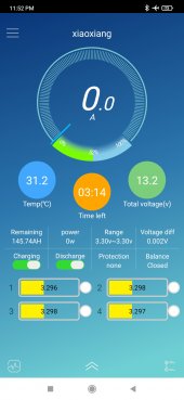
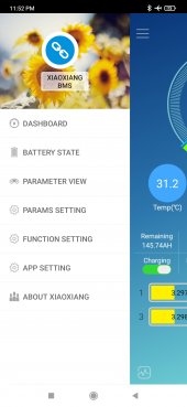
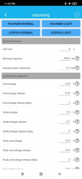
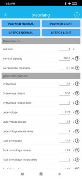
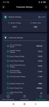
The Programmable Battery with the Bluetooth BMS App has preset defined user profiles and you can also manually adjust many parameters. I took screenshots of LIFEPO4 Normal (Img3) and LIFEP04 Light (Img4), and they are within proper spec. I use the light settings. And it works great, 2 plus years and no issues, top balance healthy pack, no deviation on the cells. Etc.

I do not mean to but heads again, or argue about weather I should use the BMS to turn off the charge cycle or not, I literally don't have any other way to stop the charge cycle. I just replied to Supervstech, who you were replying to to confirm his correctness. I am not judging, and I will not tell you how to operate your system, but I will say, I think I brought up a couple good points; so I will quote them, and I would like to know your take on these points. And if you can, read the terminal voltage of your SCC and Battery. Don't unplug, turn off or disconnect anything, just take a quick looksee. I am trying to get a broader data set. If you can, and don't forget, I do appreciate everyone's help, their input and wisdom. Thanks man.

"
It is too early to make any decisions on my final MPPT Parameter settings until I make sure ALL cables are large enough, and triple check all connections, etc. But I already know that the default LFP setting for this MPPT Controller doesn't cut off the voltage when the battery is full, that is handled by the BMS on the Battery. I ran the system in the default settings for the first week and I charged up the system to full, twice. Both times; the BMS turned off the charging cycle, it literally flipped the charge toggle off, and I could not manually turn it back on until the "Charge Voltage Disconnect Release Voltage" was hit. Then it would toggle charging back on. Or allow me to manually toggle it.

I had a non-programmable Renogy Wanderer 30 Amp LFP Version Charge Controller for 2 years and the only way to stop charging was when the batteries BMS would kick in and stop the charging cycle. That was how it was designed to work and it worked great for 2 year.

This new MPPT charge controller has a "LI" setting that is explicitly for LFP and it too works just like the Renogy Wanderer, the only way the charge cycle stops is when the Batteries BMS kicks in.

This new MPPT also has a "USE" setting for User Programable Parameters, but again, there IS not High Voltage Disconnect setting and the only way the charge cycle is stopped is if the batteries BMS stops the charging into the battery.

I do realize a lot of people in the forum are saying the same thing as you, that I shouldn't use the battery BMS to stop charging, but that is literally how its designed to work. I literally have no other way to stop the charge cycle unless I would sit there and manually do it, and you know that is practically impossible.

And then there is the Wall Chargers that I have, designed for LFP, they do not stop sending current and the only way I know my battery is fully charged is when the BMS says 100% and stops the charging.

And, on top of that, all the advertisements around new LFP batteries talk about "Lead Acid Drop In Replacement" meaning these Batteries are designed to work with a wide range of hardware designed for 12v Lead Acid Equipment. Including Lead Acid Chargers, Inverters, etc - these devices cover a wide rang of usage scenarios and parameters, and LFP batteries with internal BMSs are designed with this in mind, meaning the BMS was designed to be used to disconnect the current once the battery is charged. That, and many other conveniences of modern electronics like cell balancing functions, over-current, over-charge, reverse polarity, over-discharge, etc - all these functions are built in and guaranteed by the battery manufacturers.

If they fail, its the manufacturer who will have to cover the replacement costs, at the least. (And I don't want to get into the minutia of fly by night cheap sellers, etc, that is not the point... though it is a consideration)

With what you have said, as well as so many others in this forum, (thank you by the way) - what do you recommend I do.

What system are you running? Do you have modern hardware? Do you have LFP, or Lead Acid?

What Charge Controller are you using? What is the reading at the posts of your charge controller terminals, and battery terminals during peak sun? Do you see any Vdroop?"

Thanks again.
 

Attachments

  • Img1.jpg
    Img1.jpg
    221.9 KB · Views: 3
  • Img2.jpg
    Img2.jpg
    181.3 KB · Views: 3
  • Img3.jpg
    Img3.jpg
    124.6 KB · Views: 3
  • Img4.jpg
    Img4.jpg
    124.6 KB · Views: 3
Hi, I am sorry if you already read one of my replies regarding this. I'm looking back at the posts and trying to gather as much information and learn as much as I can, and everyone is pointing out this Voltage Drop, or whateveritis... and I am on it. Thank you.

I am already planning on changing out the cable to High Quality #6 cable and when I do that I will double check all the connections. I did not remember about the CCA cheap cable info, but I do remember Will talking about it in one of his videos years ago.

And just to confirm; YES, the 1 Volt delta from the Charge Controller to the Battery is very much a concern for everyone, as everyone has stated. And I will be replacing the wire and I will make sure to report any progress and changes. Thank you again for the help and the great information from this community - thanks

PS: Do you have a similar 12/24/48 volt system. (6x100w Panels, 40Amp MPPT & 200Ah/+ LFP Battery) - I would love to know what other people with comparable systems are seeing at Peak Sun, I would like to see what their Controller volt reading, and the Battery volt reading. Anyway - Thanks Again.
You didn’t mention your ground wire lenght or size from battery to charge controller?


this video might be also usefull for you when you start looking for the exact cause of voltage drop:
 
Just to reiterate what others have said, it could be anywhere in that circuit, not just the wire. Have you tried the voltage drop test recommended earlier at several points along the wiring path? It was even suggested to run the test on both legs of the wiring to help determine if it is in one or both sections or a connection or two that are adding up to create a one volt drop in voltage.
Oh, hey man, Thanks. Yea I just want to say thank you to you all everyone who has been so helpful with my system. There are many issues to investigate and resolve. but as I said to several other people, I will be upgrading the wire to high quality 6AWG, and I will double check, triple check, each and every connection to make sure things are goodntight, not corroded or even slightly tarnished, etc.

I have not checked the wire from one end to the other mainly because the system is under the kitchenet, and I have to take the countertop off, and I am going to be tearing the whole system apart tomorrow anyway.

Using 6 AWG Cable, I will connect the Charger DIRECTLY to the Battery, which I just checked, is at about ~50 SOC, so that will be perfect when peak sun hits tomorrow, I can get a good clean reading from terminal to terminal, as well as report the readings from the Apps.

Hey, while "I got you on the line" - let me ask you; what is your system configuration. Do you use Lead Acid or LFP. Do you have an MPPT?

Could you do me a favor, could you go out and read your voltage at the Charger Terminals, and the Voltage at the Battery Terminals. I am trying to get as large a data set as possible. - Thanks again for all the information and the great community. (Tell my your hardware specs as configured, your usage, etc. thks!)
 
there IS not High Voltage Disconnect setting
Someone earlier asked if there was a setting for Bulk or Absorb voltage? I tried to look through both threads and could not find an answer to that question. Sometimes the terms are obscured but CV (Constant Voltage) is sometimes used to describe the point where the charger transitions from Bulk (Constant Current) to Absorb (Constant Voltage)
 
You didn’t mention your ground wire lenght or size from battery to charge controller?


this video might be also usefull for you when you start looking for the exact cause of voltage drop:
Hi, when you say "ground wire length" are you talking about the "Black Negative Wire" - if so, it is the same size as the Positive Negative Wire.

As for a "Ground, Ground" - like in modern home AC systems. There is no ground from the panels to the controller, battery, or inverter. They are all connected ONLY by positive and negative cables. My Charge Controller may be grounded because it is screwed to the metal in my RV.

Do you think I should try to ground all the components to the chassis of the RV? My system is small, and all documentation I have seen either has no mention of grounding instructions, or grounding is not necessary. What do you think.

Also, I have been asking people to take a reading of their Charge Controller Terminals and Battery Terminals at Peak Sun, so I can build a baseline of what is actually being reported "in the wild" and have some data sets to compare. If you could do that it would be greatly appreciated.

PS: Also spec out your system, and how you use it. Thanks again for all the great information and community.

PPS: I am tearing everything apart and swapping out/upgrading the wire tomorrow, checking all the fittings and connections and I will connect the charger directly to the battery and take a reading with the larger #6 wire and report the findings - thanks again!
 
Hey, while "I got you on the line" - let me ask you; what is your system configuration. Do you use Lead Acid or LFP. Do you have an MPPT?
I use LFP
Could you do me a favor, could you go out and read your voltage at the Charger Terminals, and the Voltage at the Battery Terminals. I am trying to get as large a data set as possible. - Thanks again for all the information and the great community. (Tell my your hardware specs as configured, your usage, etc. thks!)
I have an All In One hybrid Inverter and the charger terminals are also the load terminals. I only have a Class T fuse and a Contactor on that path which is 8 feet round trip. Tonight there is a small load but I will take measurements in the morning during full sun when it should be charging at 60 to 80 Amps.
 
Someone earlier asked if there was a setting for Bulk or Absorb voltage? I tried to look through both threads and could not find an answer to that question. Sometimes the terms are obscured but CV (Constant Voltage) is sometimes used to describe the point where the charger transitions from Bulk (Constant Current) to Absorb (Constant Voltage)
Yes, there is a "boost" voltage - see pic

Hey, while I got you, what are your system specs? Can you yell me how you use your system &, if you can, under peak sun, tomorrow, please take a reading at the terminals of your Controller and Battery. I am trying to build a dataset for reference. Thanks man.

PS: The only other setting that is not in screen is the "Light Control Voltage" - which is basically for using your solar panels/charge controller as a night light - when the panel voltage hits (their default of 5v) a certain voltage, you can connect a set of lights to the "load" terminals on this Controller and it will turn on the lights. Basically a fancy night light. Could be useful but I do not have anything connected to the load terminals on this controller.

Oh, and there is a temp compensation parameter, default is set to the lowest possible setting and there is no toggle to completely disable it for LFP.

All the setting you are looking for are in the image...

Oh wait there is also a setting for Equalization Intervals, I set it to zero days.

EDIT: PS: What kind of usage do you use your system for, heavy daily cycling, or secondary loads, light loads? Is your system mostly fully charged etc. As I said, I have been trying to get my system robust enough so that if/when SHTF, I can run it for prolonged periods of time with heavy daily loads. Im not really there yet, but I might be able to squeeze in 2 more panels, and another battery, but its really packed as it is. And its not quite powerful enough, and that is in full blast summer sun, so... yea, now that I think about it...
 

Attachments

  • Screenshot_2022-08-26-12-11-11-282_com.paoding.heli_solar_app.jpg
    Screenshot_2022-08-26-12-11-11-282_com.paoding.heli_solar_app.jpg
    123.2 KB · Views: 7
Last edited:
Yes, there is a "boost" voltage - see pic
One way to have your charge controller stop charging before your BMS cuts off would be to set the Boost voltage to a value lower than the high voltage disconnect of your BMS. Boost is just another term for Constant Voltage or Absorb. A setting of 15.2 for Constant Voltage is 3.80 volts per cell and that is why your BMS is disconnecting before your charge controller. With your voltage drop that is 3.55 per cell. However if your charge controller does transition to CV mode the current probably tapers and your voltage drop may reduce which could increase the voltage at the battery to the point that your BMS has to cut off charging.
I am trying to not take my pack higher than 95 per cent so my setting is 3.45 per cell. My BMS high voltage disconnect is 3.60 volts per cell. I will describe my system and how i use it tomorrow when I check voltage under full sun.
 
Last edited:
Well, I just ordered 3' 6AWG Silicone Tined High Amp Wire. We will see.. I know for sure there is some resistance form the wire. But as someone (Browneye) stated in the comments above;

"The battery voltage displayed on the SCC is with the charge current added on top of the system or battery voltage level. It is common for it to read a little higher at the SCC. Again, the only way to get a true volts reading on a battery is after resting with no load or charge current. At that point, your SCC and battery should pretty well read the same. With charging current it is going to read higher at both the SCC as well as the actual battery, and any meters you employ. At least that has been my experience."

Your are using this comment and drawing incorrect conclusions , a battery under charge has an equivalent resistance. The resulting battery terminal voltage is defined by ohms law , given that there’s such resistance and a finite small resistance in the wire. It’s usually that the SCC voltage is marginally higher , this higher voltage is SOLEY down to the resistance of the wire and any voltage difference is lost as heat in the wire.

What’s absolutely technical nonsense os the charger voltage is higher then the battery terminal voltage to push more current. That’s technically IMPOSSIBLE. Yes given a powerful charger you can raise the charger voltage and yes more current will flow into the battery ( usually if it’s not fully charged ) but the battery terminal voltage , ie at the wire end is the same as the charger , less any resistance drop due to the wire.

Your suggestion to allow the charger to rise to 15V when your BMS cutoff of set lower is USELESS , with a proper low resistance cable. The bms will disconnect the battery when the charger voltage exceeds its setting

Note HVC should not be used to terminate charge anyway
 
My readings were

One way to have your charge controller stop charging before your BMS cuts off would be to set the Boost voltage to a value lower than the high voltage disconnect of your BMS. Boost is just another term for Constant Voltage or Absorb. A setting of 15.2 for Constant Voltage is 3.80 volts per cell and that is why your BMS is disconnecting before your charge controller.
I am trying to not take my pack higher than 95 per cent so my setting is 3.45 per cell. My BMS high voltage disconnect is 3.60 volts per cell. I will describe my system and how i use it tomorrow when I check voltage under full sun.
Correct , this is the way to do it. Bms HVC should be an error condition not a charge stop point
 
My readings were

One way to have your charge controller stop charging before your BMS cuts off would be to set the Boost voltage to a value lower than the high voltage disconnect of your BMS. Boost is just another term for Constant Voltage or Absorb. A setting of 15.2 for Constant Voltage is 3.80 volts per cell and that is why your BMS is disconnecting before your charge controller.
I am trying to not take my pack higher than 95 per cent so my setting is 3.45 per cell. My BMS high voltage disconnect is 3.60 volts per cell. I will describe my system and how i use it tomorrow when I check voltage under full sun.
Oh yea, man. I totally agree with you; that sweet spot of 3.45 for both charge and disconnect voltage would be great! But I recently have been running in parallel a second super cheap 200Ah Chinese Battery with no BMS App or settings, and so, I picked 3.55v - a balance between the batteries. I think the cheapo battery disconnects at 3.6 because they do disconnect at about the same time, but I have not babysat them to see the exact voltage the cheapo turns on/off. They are close. But if I could, I'm all about that sweat spot of 3.45.

And so you know, and I did state this in my crazy controversial post about how I configured my charge controller, when I run my system, it is never full, and when I don't use the system I charge it up, and then disconnect and turn everything off...

I also did say very clearly at the top of the post that this system isn't perfect, but it not only works, and I ACTUALLY AM able to get a lot more power of of the system, all be it at the cost of what I consider to be overly cautious "industry norm" parameter settings...

As well as I go through the whole shabang of qualifying exactly what components are in the system, clearly stating its for small LFP systems that do not have data sharing etc. We are getting there - Resolve the Delta discrepancy, is it the wire, is it only my system, is it still a problem with a larger wire connected directly to the battery from the controller... etc.

Thanks again for the help and information, its been really great working with such a knowledgeable community.
 
Status
Not open for further replies.

diy solar

diy solar
Back
Top