diy solar

diy solar

DIY 24-volt 560Ah LiFePO4 battery (272x2=544Ah) with Electrodacus SBMS0 and Electrodacus DSSR20

yes, the arc is quite scary and does wake a person up as to safety-type things. thanks for sharing. yesterday I bought 20 2 piece sets of plastic cutting mats from the dollar store for a dollar each. so I got 40 pieces. Each piece will be big enough to insulate between 2 of my 272Ah Lishen cells. I also bought a melamine coated shelf board 24" x 48" to use as a slick insulating base for the compression jig for the 2P8S 24-volt battery banks I am charging and assembling. I think the cutting board mats are a very inexpensive durable inter-cell insulator. just an idea for you. yes, I still need to insulate my tools better. I am very careful after the 1st arc I had. woo hoo the sparks and power. all DIY people need to beware of the high power --- for sure. Keep up the excellent work. I have 64 cells and I am building 4 24-volt packs of 16 cells each. the 1st 16 cells (272Ah Lishen cells) 2P8S 24-volt pack is charging the other 32 cells with 2 bench chargers one Riden 6012w and the other a Riden 6018w running 24/7 off-grid via the 24-volt inverter. sorry... I am rambling!!! :cool:
 
Nice system! What relay/contactor(s) do you have connected to the SMBS0 control power in/out of the batteries? Also, do you have a precharge circuit for the inverters?
 
no precharge circuit to the inverter. I used a resister and precharged the capacitors in the LF PSW split phase 6000 watt inverter before I hooked it up(there was absolutely no spark that way). the Electrodacus DRRS20 are the solar charge controllers. no MPPT needed. the DSSR20 is a solid-state relay and charges the LiFePO4 batteries great. on a cloudy day like today with a little ice coming down, I was getting about 120 to 150 watts out of the 6 250 watt panels but when the sun is shining I was getting close to 1300 watts for charging the 24-volt 2P8S battery bank.
right now I just manually turn the inverter on and off without any problems.
I changed two cables in the battery bank today to 2 gauge(with correct size lugs) so I shut the inverter off; but otherwise, it is running 24/7.
the Electrodacus SBMS0 turns the Electrodacus DSSR20's off when the battery is full.
I have 10 panels hooked up but 4 of the panels do not get any sun until late in the day as they are facing west. the 6 south facing panels do great.
 
If cells are new you do not need any manual cell balancing just connect them and the small imbalance will be corrected over time by the SBMS.
the electrical engineer Dacian said that.
I will do that on one 24-volt 2P8S battery bank build using 16 272Ah Lishen cells for sure as the top balance and charging on the new cells is a very very slow process.
The terminals on the Lishen 272Ah cells are small and use M6 bolt or studs --- I highly recommend you use M6 studs that are 20mm long. that way when you place the interconnecting bus bars you are less likely to accidentally arc between cells. the 6mm diameter studs us a serrated flare nut and a 10mm wrench is required or better might be a deep well socket with a 1/4 inch drive ratchet.....do not overtighten these 6mm studs or you will strip them and be sorry.
I bought some permatex to use instead of lock-tite to secure the studs.
yesterday I changed the cable between cells 4 and 5 to a larger 2AWG copper battery cable with Selterm 1/4 inch holes for a better connection as it seemed there was a slight charging issue between those 2 cells.
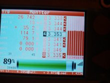
Selterm tinned copper lugs are what you will want to buy. buy yourself a hydraulic crimper or have the cables made for you. I am making all my cables with proper crimping tools and heat shrinking as necessary. through the clouds and snow, I am still getting 114.7 watts to the battery from the 6 south-facing 250-watt panels in parallel sets of 2! :cool: snowing again here and will be for a lot of days to come.
need a longer handle on my push broom to clean them off a bit(the solar panels). 14 degrees Fahrenheit this morning. hate the cold!
 

Attachments

  • 20210125_102458.jpg
    20210125_102458.jpg
    57.4 KB · Views: 7
Last edited:
yes and no. I used a bench charger to initially charge the cells but never got them close to 3.65. too impatient. I hooked up 16 cells 2P8S for a 24-volt battery bank and used the SBMS0 to charge it up more with the solar panels; of course, I have the inverter connected for the load and I have dc lights and I also have 2 chargers running off the 24-volt battery bank (2P8S Lishen 272Ah 16 cells); one charger is charging 8 272Ah cells in parallel for the top balance of those 8 cells at 3.5 volts right now - I will move it up to 3.65 later; the other charger is charging 8 272Ah cells connected in series(for an 8S 24-volt battery) @27.5 volts. both chargers are running off the inverter off-grid from the solar electricity produced yesterday. the inverter has been running off-grid 24/7 charging the new 32 Lishen 272Ah cells. when the sun is out it is getting about 1200 watts charging the battery and also running the load out of the battery. yesterday the battery was fully charged at about 1 or 2 in the afternoon. I turned on the dc lights, ac lights, and turned up the bench chargers.
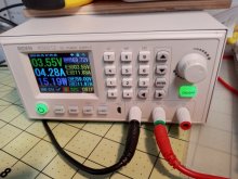
the 2 very accurate bench chargers I am using are Riden 6012w (60 volts at 12amps max charging) and Riden 6018w (60 volts at 18 amps max) which are plugged into the inverter so they are running off-grid 24/7 at the moment.?
the SBMS0 brings the battery back up to full charge in a few hours of good sun. just exercising some of the Lishen cells as I increase capacity etc. I bought Seltern 1/4 inch tinned copper lugs(arrived yesterday) to make a few cable interconnects with 6 gauge wire to balance and parallel balance some more cells. the cells only came with 4 busbars per 4 cells --- but in reality, a person needs twice that many busbars ( to parallel top balance 8 cells need 16 bus bars to interconnect 8 cells at the same time).
I think the SBMS0 could do all the charging for the new Lishen 272Ah cells, but most members on the forum reccomend doing a top balance 1st.
I believe the SBMS0 can do it alone and have implemented that on 2 8S battery configurations.?

Attachments​

  • 20210122_024230.jpg
    20210122_024230.jpg
    81.2 KB · Views: 0
  • riden 6018 pic.jpg
Just a suggestion (you may already know it). Use the black and green connections and it knows you are charging a battery.
The 800 watt supply these ship with is a consumer grade power supply, and on the 12 amp version you are pushing 720 watts at 60 volts, 12 amps. The power supply will die within an hour. The 18 amp one also has a bundle with the same 800 watt supply, but should work fine for a 24 volt battery (i.e. 28v at 18 amps is a little over 500 watts). There are some great reviews and analysis of the supply, including how to use $2 worth of parts to get the 12 amp version to sustain the maximum 720 watt output, but it does require soldering.

Jerry Walker is great, I might be prejudiced since he is busy restoring devices I worked with for many years for museums (Intel MDS and Fluke 9010). You know you are old when the computers you started with are going into museums.

RD6012 assembly part 1
RD6012 and how to kill it part 2
RD6012 how to make it not die with $2 part 3
RD6012 how to make the fan more quiet part 4

I will admit, I just replaced both fans internal to the unit with Noctua, makes a big difference in the noise level.
I'm currently waiting on the parts for the fix to the power supply to arrive from China.

He also has an earlier series on the RD6006, the original 6 amp version. He even shows you how to build a linear supply for it to reduce a lot of the noise on the output (we don't really care when charging batteries). Including winding the transformer for the linear supply, it like a 16 part series, so I won't link to it here.
 
no precharge circuit to the inverter. I used a resister and precharged the capacitors in the LF PSW split phase 6000 watt inverter before I hooked it up(there was absolutely no spark that way). the Electrodacus DRRS20 are the solar charge controllers. no MPPT needed. the DSSR20 is a solid-state relay and charges the LiFePO4 batteries great. on a cloudy day like today with a little ice coming down, I was getting about 120 to 150 watts out of the 6 250 watt panels but when the sun is shining I was getting close to 1300 watts for charging the 24-volt 2P8S battery bank.
right now I just manually turn the inverter on and off without any problems.
I changed two cables in the battery bank today to 2 gauge(with correct size lugs) so I shut the inverter off; but otherwise, it is running 24/7.
the Electrodacus SBMS0 turns the Electrodacus DSSR20's off when the battery is full.
I have 10 panels hooked up but 4 of the panels do not get any sun until late in the day as they are facing west. the 6 south facing panels do great.
If you are lazy like myself, and like the "neat" approach, REC has a nice (and expensive) precharge setup.
 
Just a suggestion (you may already know it). Use the black and green connections and it knows you are charging a battery.
The 800 watt supply these ship with is a consumer grade power supply, and on the 12 amp version you are pushing 720 watts at 60 volts, 12 amps. The power supply will die within an hour. The 18 amp one also has a bundle with the same 800 watt supply, but should work fine for a 24 volt battery (i.e. 28v at 18 amps is a little over 500 watts). There are some great reviews and analysis of the supply, including how to use $2 worth of parts to get the 12 amp version to sustain the maximum 720 watt output, but it does require soldering.

Jerry Walker is great, I might be prejudiced since he is busy restoring devices I worked with for many years for museums (Intel MDS and Fluke 9010). You know you are old when the computers you started with are going into museums.

RD6012 assembly part 1
RD6012 and how to kill it part 2
RD6012 how to make it not die with $2 part 3
RD6012 how to make the fan more quiet part 4

I will admit, I just replaced both fans internal to the unit with Noctua, makes a big difference in the noise level.
I'm currently waiting on the parts for the fix to the power supply to arrive from China.

He also has an earlier series on the RD6006, the original 6 amp version. He even shows you how to build a linear supply for it to reduce a lot of the noise on the output (we don't really care when charging batteries). Including winding the transformer for the linear supply, it like a 16 part series, so I won't link to it here.
I never understand the green and black connection. I have been using the red and black connection. the Riden 6012 has been running for days. I will experiment a bit. they register how many amps and how many watts have been sent to the batteries. I bought a 1200 watt power supply to go with the Riden 6018w. both have been working fine, but I still need to further investigate the green and black connection for battery charging as you suggest. I watched some of Walker's videos but he seemed to tear the power supply apart which was not required to mount in the case.
thanks for the heads up -- will work on it.
I have also ordered 1200 watt supplies (I have two of the RD6018w), waiting for shipping from China.
I have one of the RD6012w with the 800 watt supply, waiting on the parts from China to modify the supply (had to order 50, so if anyone is interested, contact me).

When using the green connector, it just knows you are charging a battery. So when the set voltage is reached, and the amps output drops to .1 amp, it will terminate the output. Just makes it easy to avoid over charging. Not really a must have feature, but it is convenient (and very reliable).
I noticed the dropping of amps and watts as the batteries were getting charged when using the red and black connections. but I changed now to the green and black and the battery charging icon lights up as red with a green battery icon. I am charging 8 272Ah Lishen cells in parallel from the inverter from the functioning 24-volt 2P8S battery bank off-grid from solar power. the sun is out again after the 2 inches of snow and the 6 250-watt panels are putting out about 1300 watts into the battery & inverter load.
what is the difference between the red and green posts on the Riden??????
I have both 6012w and 6018w functional without any problems.
thanks in advance.
yes, I used the 1st computers 40 years ago and many operating systems but not my specialty. with the 1200m baud modem and 5.25 disc etc scsii etc before usb. i built computers for a few years and still dable.
solar is my new electric hobby. studying it for years.
the 6018w came with an extension cable for the battery temperature sensor that I did not use as there was no mention of how to use it . it plugs into the back of the power supply on the 1200watt power supply and impossible to get to it once the 1200 watt power supply is mounted into the case. essentially one would have to disassemble and reassemble it.
 
Last edited:
If you are lazy like myself, and like the "neat" approach, REC has a nice (and expensive) precharge setup.
not sure if the precharge would help me out or not but will investigate that. I have no automation to turn the inverter on and off at this time.
thanks for your input.
I like the saying: "a lazy man is a smart man; a smart man is a lazy man"
 
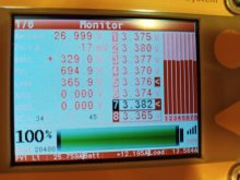
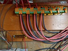
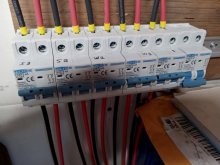
Riden 6012w pics etc January 26th, 2021, also 32 Amp DC bipole breakers for every 2 solar panels, 5 Electrodacus DSSR20's wired and operating; and of course Electrodacus SBMS0, trying to turn on more load to use the sun even though hazy out it charged the battery quickly today after the 3 inches of snow stopped about 8 a.m. this morning. I use the breakers to turn the panels on/off during assembly as I hook it all together. essentially never get shut off again --- but you never know as I rearrange to suit my project. the 5th or 1st installed DSSR20 is not in the picture as it is located down to the left out of view! sorry!
 

Attachments

  • 20210126_132713.jpg
    20210126_132713.jpg
    74.7 KB · Views: 43
  • 20210126_132747.jpg
    20210126_132747.jpg
    64.1 KB · Views: 47
  • 20210126_132759.jpg
    20210126_132759.jpg
    90.5 KB · Views: 52
  • 20210126_132812.jpg
    20210126_132812.jpg
    67.1 KB · Views: 54
Last edited:
The Electrodacus SBMS0 electrical engineer states:
"The amount of cell balancing current is not relevant but the way cell balancing is done is. Some less advance BMS just start balancing based on single cell voltage and say for LiFePO4 they start balancing when cell is above 3.6V not considering the voltage of other cells thus this sort of cell balancing is completely useless even if they try to balance at very high currents as cells should never be at that voltage and even if they are there it will be just for a few seconds not even minutes as from above 3.5V cell voltage increases fast in seconds if charging is not stopped.
The SBMS0 is based on the Intersil ILS94203 and this will balanced as soon as there is a minimum of 300mA of charge current and as soon as there is more than 10mV delta between any two cells thus it can balanced for many hours each day if needed and in total it can handle way more energy due to long balancing time even if at low currents. Balancing 30 seconds at 1A is the same as balancing 5 minutes at 100mA
Same type of balancing used by the SBMS0 is used in all commercially available EV's including Tesla."
:cool:
 
If cells are new you do not need any manual cell balancing just connect them and the small imbalance will be corrected over time by the SBMS.
the electrical engineer Dacian said that.
Just a note, from what I recall Dacian's two packs have been top of the line grade A small A123 pouch cells, and Grade A, GBS cells. I don't think he is very familiar with or recommends variable quality grey market cells. The unmatched, non-grade-A (or at least not consistently Grade A) large form factor cells popular on this forum are somewhat of a different beast. Both because each cell contains so much more energy, and because being unmatched and unqualified there are bigger differences between cells than would be typical with cells bought through legit retail channels.

I'm not saying he is wrong, or that what he is saying will not work for you, its a valid approach. In theory he is right, letting the BMS do the work over time or manual top balancing will in theory lead to the same result. Manual top balancing is just quicker and more consistent. But the larger the cell size and the larger the mismatch, the harder and longer the tiny BMS balancer will have to work to bring the cells inline, and there may be a point where the BMS is incapable (or at least that's how I understand it, and one reason you see many people opting to add active balancers to their EVE packs). If you are lucky and your cells are pretty well matched/balanced (or if you don't mind operating at reduced capacity for some time) this may not be an issue for you, but many people have found that it is. You may want to follow up with Dacian and make sure that your situation (cell size, and unmatched+unknown grade) matches his assumptions.
I have a 12mv difference in my 2P8S 24-volt 272Ah Lishens right now with 95%state of charge. they were at 100 percent earlier today so I turned on a larger load on the inverter and dc light direct from the battery bank.. my cells all came in with matched voltages when they arrived. I will ask Dacian for a bit more input.
Will Prowse also indicated that new cells do not have to be top balanced or bottom balanced in some of his rethinking in his testing of new cells. if they are matched. as i recall from his youtube videos. I set mine at 544Ah as being full in the SBMS0. they don't charge above 3.55 volts as that is 99 percent full and above that, you risk permanently damaging the cells with little if any gain in capacity.100 percent is when they are at 3.55volts. the SBMS0 stops charging at 3.55 volts so the cells will not be damaged. 6 250-watt south-facing panels (in parallel 2P thru 3 DSSR20's) push up to 45 amps at the battery in full sun and charge fast. I get 120 to 600 watts in overcast or cloudy days. still charging the battery.
open circuit is about 36 to 38 volts then when they hit the 2p8s 16 cell 13,926.4 Wh Lishen 24-volt battery bank the voltage is brought down to about 28 volts or so and pushes as many amps as they can without overcharging them. the dssr20 is a solid-state relay. no mppt needed.
 
Last edited:
  • Like
Reactions: Dzl
I have a 12mv difference in my 2P8S 24-volt 272Ah Lishens right now with 95%state of charge.
That's great, in this case you may well have no need to balance. how are you measuring 95% SOC, and what voltage did this correspond to?

my cells all came in with matched voltages when they arrived.
That's normal and (as far as I understand) not necessarily very indicative of how well matched or balanced cells will be

Will Prowse also indicated that new cells do not have to be top balanced or bottom balanced in some of his rethinking in his testing of new cells. if they are matched.
This is the important point. If cells are well matched and at nearly the same state of charge it may not be necessary. If you are buying cheap cells from a reseller they are not matched (verb -- as in nobody has performed the process of matching and batching them) there is a chance they will turn out to be decently matched (adjective--as in they happen to be well matched despite not going through the matching / batching process). Resellers of discount cells do not do cell matching at this price point. They check resting voltage and maybe IR, but do not do matching (particularly capacity matching).

From the sound of it, you have already configured and cycled your pack? And the cells are sticking together as a group when you charge and discharge? If so, it sounds like you are in good shape and may have no need to worry about top balancing. Balancing only corrects imbalance, if there is no substantial imbalance, there is nothing to correct, or at least nothing that can't be handled by the BMS. Top balancing also ensures that mismatched cells are most balanced at the top (and least balanced at the bottom) which is beneficial because (1) its easier to set your charger and BMS limits when you top balance (2) in most scenarios you spend much more time towards the top of the SOC spectrum than the bottom (3) your BMS balances at the top, so its really the only logical choice.
 
dequately
That's great, in this case you may well have no need to balance. how are you measuring 95% SOC, and what voltage did this correspond to?


That's normal and (as far as I understand) not necessarily very indicative of how well matched or balanced cells will be


This is the important point. If cells are well matched and at nearly the same state of charge it may not be necessary. If you are buying cheap cells from a reseller they are not matched (verb -- as in nobody has performed the process of matching and batching them) there is a chance they will turn out to be decently matched (adjective--as in they happen to be well matched despite not going through the matching / batching process). Resellers of discount cells do not do cell matching at this price point. They check resting voltage and maybe IR, but do not do matching (particularly capacity matching).

From the sound of it, you have already configured and cycled your pack? And the cells are sticking together as a group when you charge and discharge? If so, it sounds like you are in good shape and may have no need to worry about top balancing. Balancing only corrects imbalance, if there is no substantial imbalance, there is nothing to correct, or at least nothing that can't be handled by the BMS. Top balancing also ensures that mismatched cells are most balanced at the top (and least balanced at the bottom) which is beneficial because (1) its easier to set your charger and BMS limits when you top balance (2) in most scenarios you spend much more time towards the top of the SOC spectrum than the bottom (3) your BMS balances at the top, so its really the only logical choice.
Will Prowse does not buy matched cells any more than what anyone else receives from China. he buys market cells that arrive with matched voltage but not perfectly matched and balanced. ask him
my cells all arrived in new condition and were purchased as such. the Electrodacus SBMS0 actively balances the cells when charging from the solar panels. Every day it is charging and balancing the battery bank cells 2P8S 24-volt 272Ah Lishen 16 cell battery bank. so it is a 544 Ah 24-volt battery bank(conservatively). the vendor says they will do up to 285 Ah but no need to try to burn them out. I will have 4 24-volt 2P8S 16 cell battery banks of 272Ah Lishen cells. each 24-volt 2P8S battery bank will be actively monitored and balanced by an Electrodacus SBMS0.
3.2volt/cell x 272Ah x 16cells = 13,926.4Wh per 24-volt battery. 4 24-volt battery banks = 55,705.6 Watt-hours potential capacity.
the off-grid inverter is running 24/7 right now. I am presently charging 8 272Ah Lishen cells in parallel with the Riden 6012w from the 24-volt solar power off-grid. this is a DIY off-grid build and at the moment is functioning great and better than the naysayers state.

the Electrodacus SBMS0 3 decimal place accuracy matched up with my multimeter 2 and 3 decimal place accuracy
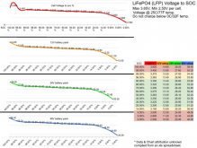
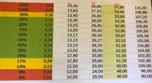
I will look for the state of charge chart I received from the vendor. and post in this forum again.

the Electrodacus SBMS0 controls the charging through the Electrodacus DSSR20's and turns them off at 3.55volts with some delay so the battery cells are not permanently damaged.
there is no real gain by charging them to 3.65Volts only the possibility of shortening their life-span.
all the amperage goes through the Electrodacus DSSR20's up to 24 amps per DSSR20. (they are capable of 24 amps each)
I have 3 connected to 6 250 watt south-facing PV panels doing all the charging at this moment I also have 4 250 watt panels with 2 dssr20 facing west, but get no sun until later in the day.
6 250-watt polycrystalline panels put out up to 1300 watts at up to 45 amps in this off-grid system in full sun to charge the battery and run inverter loads.

I will be adding more panels and use excess solar to heat water and heat the house etc.
next priority is ac panel wiring directly to inverters.
 
the Electrodacus DSSR20's are solid-state relays that are controlled by the Electrodacus SBMS0. the DSSR20 is the solar charge controller.
the SBMS0 is the BMS and the monitor and brain for protecting the expensive LiFePO4 24-volt battery bank.
THE DSSR20 is not an MPPT charge controller and it is not a PWM charge controller; it is a solid-state relay that gives the LIFePO4 battery all the solar panels will put out.
hopefully, Will Prowse can make a new youtube video that correctly evaluates the DSSR20 and the SBMS0.
for DIY the Electrodacus is second to none.
24-volt is worldwide accepted as safe voltage! :cool:
I currently have 5 connected (DSSR20's) and they work great!
 
Back
Top