diy solar

diy solar

On Keeping LFP Warm

One more update on this: In addition to the first two questions explored above (how much energy to raise temp of cells, and how much heat loss of my insulated box), I wanted to take a stab at determining the effect of charge and discharge rate on cell temp (as others have explored in this thread).

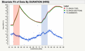
I ran a 0.1C (28A) charge cycle from 60% to 100% SOC, followed by an overnight 'cool-down', followed by a 0.1C (28A) discharge cycle from 100% to 60%. The charge cycle is highlighted in by the red box; the discharge cycle is highlighted by the blue box. Note that I tripped a breaker in the middle of the discharge cycle, which explains the 'dip' in that curve. The dip area has been excluded from the analysis. I calculated the slope of the temperature curve for a 1 hr duration at the begging of each of those cycles. For the 0.1C charge, my temperature increased by 1.39 C/hr. For the 0.1C discharge, the temp increased by 0.87 C/hr. I'm not sure what I was expecting, but I guess I was surprised to see how different these were. It seems that charging produces about 60% more heat than discharging at the same rate.

Does that align with what other's are finding?

DATA SET 2.png
 
Wow @schroederjd - That really is pretty interesting. Like you, I don't know what I would have expected, but my gut would have been that discharging would warm the batteries more than charging. I think @Bill Taylor was really only looking at discharging, so maybe that's why my head was wrapped around discharging. Of course, if your cells are getting too cold to charge you can discharge to warm them up, but you obviously can't charge.
 
After seeing this data, and thinking through the real-world implications, I'm starting to think it might not take much energy at all to keep these cells above freezing. In the plot shown above, after the charging cycle (red highlight), I opened the box and had two small fans blowing on it to cool the cells back down. Even with that, they still weren't back to ambient after 14 hrs. My point being that any heat gained from charging and discharging will get 'banked' for a long time, provided you have a well insulated box.
 
After seeing this data, and thinking through the real-world implications, I'm starting to think it might not take much energy at all to keep these cells above freezing. In the plot shown above, after the charging cycle (red highlight), I opened the box and had two small fans blowing on it to cool the cells back down. Even with that, they still weren't back to ambient after 14 hrs. My point being that any heat gained from charging and discharging will get 'banked' for a long time, provided you have a well insulated box.
Actually, the whole thing about the specific heat capacity is that once the cells are warmed - no matter how they got warmed - they will retain that heat for a while. It will be cooling down somewhat slowly with the speed partially driven by how insulated the container is that they are in. Water has some of the highest specific heat capacity there is. When you heat a pot of water to boiling, it will stay hot for quite a while after you turn off the heat, even though the pan will radiate heat out and suck it right out of the water.
 
You have ample solar and should do well.

I have a 5th wheel under a pavilion. The batteries will be outside in a box enclosure I could insulate them well as the space is available. -30F is the record cold temp in near Hinckley Reservoir , NY. Most likely the battery nominal temps would be around 0 -5F if I just left them. Bill showed in one test that his insulated battery in the 0F freezer only went down to about 20F in 12 hours or so.

From what I can see, the Battleborn heated battery is my #1 solution. The heater is inside the case. The are many individual cylindrical cells. The temp sensor is mounted to one of the top batteries. Yes, I'll pay for the better design, but it looks like the best for my use. I've watched their videos and have seen possible "financial engineering". One video stated they were charging lower than 32F. Maybe I could custom order a set with some enhancements, like cover the temp sensor with cloth insulation tape to ensure you don't read the air temp, and set the charging inhibit at 35-40F. Thanks to Will for doing the teardowns and YouTube videos.

It looks like Battle Born heated battery is consuming 1.8A, 12VDC (21.6W) about 30% of the time at 0F, uninsulated. I'm guessing 20W heating could be added to any 100AH 12VDC battery, with temperature control. I may buy one just to try it out. I could measure the heater duty cycle at different temperatures, uninsulated or with varying insulation. A 12VDC Hour meter could be simple (21.6W*Hours heating= consumed WH) A set of tests could be with the the battery powering the heater and another with an external source heating the battery.


Used AGM's may be dropping in price as most people are swapping to Lithium. There are some used AGM Trojan solar banks on craigslist. Still undecided.
I just got off the phone with Battle Born. Their heated batteries only use internal battery power. The wire from the + terminal to the small heater terminal is only a signal wire, no current. I'm guessing it turns on a power FET. Their warm up time from -20F to 32F is about 4 hours, uninsulated. That's the delay until it will accept a charge.

Charge inhibiting has a range for hysteresis. Charging is enabled at 32F when warming up, and will continue charging back down to 24F where it disables charging. This made me feel better if there was a higher charge rate. It wouldn't turn on at 24F, but would have to pass 32F to start charging.

The only way to heat the heated battery by external power is with an external heater. I still like Battle Born, but will have to go non-heated with my own heater pad to use external power for heating.
Life Blue heated "LT" model operates the heater from the charging source only. It comes on automatically whenever it sees available charge current. No manually turning it off and on, or forgetting and leaving it on unnecessarily. Also, the built-in battery monitor knows what's going to the heating pad, and what's going into the battery. With the BB, an externally mounted battery monitor doesn't know about the heater and will think all the current is going into the batteries.
 
Life Blue heated "LT" model operates the heater from the charging source only. It comes on automatically whenever it sees available charge current. No manually turning it off and on, or forgetting and leaving it on unnecessarily. Also, the built-in battery monitor knows what's going to the heating pad, and what's going into the battery. With the BB, an externally mounted battery monitor doesn't know about the heater and will think all the current is going into the batteries.
From what I just heard from Battle Born is that the charge will be inhibited, but internally the battery will be dumping current into the heater. Thanks for the heads up on "Life Blue". There are a ton of brands and models, each one a little different.
 
From what I just heard from Battle Born is that the charge will be inhibited, but internally the battery will be dumping current into the heater. Thanks for the heads up on "Life Blue". There are a ton of brands and models, each one a little different.
I looked around at Life Blue batteries. They didn't appear to be a reliable supplier. I've read more and more, and realized that Battle Born is the best for me at this time.

I like the multiple cylindrical cells. You have some redundancy if one or more fail. Also, they have less gadgets/bells and whistles. I trust their cold charging inhibit more than others that Will has reviewed. I bought 2 of their unheated batteries for trying out. I'll try them at freezing to make sure they don't charge when too cold.

I'll add a heater and insulation, working on using my solar power to heat the battery instead of internal power. This is a lot easier if I can trust the BMS not to charge cold. I can just feed the camper with solar, truck alternator, or generator converter. The heater will turn on when the batteries are cold, off when they reach temp.

My BigBattery battery BMS is perfectly inhibiting charging below freezing. When it hits 1C, it turns on, colder than that and its off. I was trying to charge it with 200W of solar panels, but it was below freezing. No charge happened. I had the camper 12V power fed by the solar only. The camper has a 3W parasitical load. The solar panel powered the 3Watts on then off all day. The propane/CO2 sensors were beeping constantly. The battery had shut off due to low voltage.

I have the Victron SmartSolar MPPT charger. It did work well with no battery connected. They warn not to do that, but it worked. That made me feel better about unattended cold weather, hoping the BMS shutdown doesn't cause the charging to stop until a manual reset is done.

I'm thinking of adding a supercapacitor or ultracapacitor in parallel to the LiFePO4's. They seem to be more robust than any battery. You can charge them forever, kill them dead, any temperature. Having one supercapacitor could capture some of the energy from the solar when the LiFePO4's are too cold. It would also buffer the higher C rate discharges and possibly reduce cycling.

I'll poke around to see if anyone has experience with capacitors.
 
Bill,
Thanks a lot for your work. I'm also looking to "store" LiFePO4 batteries in a cold camper in the Adirondacks. My solar charge is sporadic with the snow, clouds, and generally the low solar during the winter. I was considering using the 24VDC direct solar feed (before the controller) to dump the solar heat to the batteries. IF they warmed up, the heater would shut down, feeding the full wattage of the panels to the controller and charging the batteries.

Was your internal temp sensor in between the cells in the pack, or possibly near the BMS or ambient inside air? Did you cover the sensor to insulate it from air to only read the cell surface temps?

I was concerned about using the battery's power to heat itself. If the sun was only available for a short time, then gone, it could deplete the battery by heating itself with no charging obtained from solar. Figuring .25C discharge on a 100AH battery, I could get 4 hours before the battery dies and shuts down the BMS. If I can heat the battery in 30 minutes, I get about 8 days(30 minute warmups) with no solar charge. Once the BMS shuts down due to low voltage, there could be issues with the solar controller due to the warnings (Never disconnect the battery without disconnecting the solar first).

I'd be interested in using the battery charge to heat itself with say a 30W heating pad on the bottom. I think your current 25A, 12V or 300W would be too hot for this test. .025C discharge of 30W would heat from the bottom, with some internal heating of the cells.

Is it possible to test this to get the temperature rise for different time periods? Given the dT curve, others could extrapolate startup at any temperature. Other guestimates will be necessary as your test setup would be uninsulated, any additional insulation would preserve the heat inside.

My 800W of solar panels will peak out at 80W ( for only one hour) in the winter. That's not everyday, but one out of 4 days. Usually the clear days run together, followed by days of clouds/snow. If I can self heat the battery with it's own power at .025C discharge (30W), I could theoretically switch the heater on with solar voltage, using the battery to heat itself quicker. .025C on the 100Ah would be 80 days at 30 minute warmups.

I'm new to LifePO4, and just bought one Big Battery 170Ah. I'm hoping to work a heating scheme without opening it for testing and voiding the warranty.

Thanks
Carl
I've racked my brain, tons of sketches, If/than/else pseudo code, etc. I bought some stuff to test my way too complex concepts. I think it's really simple! I just needed to see what was available for devices and inputs.

If I install the battery heaters (with a fuse/controller/over-temp snap switches) on the power from the LiFePO4 battery, it will run on the battery power. But if I install a Low Voltage Disconnect set to cut put at 13.3 V, the heater will shut off below 13.3V. The BigBattery 170AH rests at 13.3 charged, same with BattleBorn 100AH. Setting the disconnect any lower could fully deplete the battery as these don't drop off in voltage.

They recommend charging at 14.2 to 14.6V for absorption with a float around 13.8V. The LVD will only power the heaters when there is a charging current, not using the batteries power. If the sun is shining and charging current is available, the heaters will heat the battery, or if the battery is warm, it will take a charge. This works for using the generator for power, driving the truck with a DC-DC converter, or if you run jumper cables to the battery pack.

Note that you need a reliable battery BMS that ensures the charging only happens above 32F. BattleBorn says they only turn on charging above 32F, but will continue down to about 24F. This seems excellent as Will P has shown the BMS temp sensor is on one of the cells. Also, I've been trying my BattleBorns out with solar charging, no heating. They will not accept a charge until about a day over 34F.

The same was with my BigBattery. It would not charge until a day over freezing.

The hardest part was to find a LVD switch that I could set to 13.3V cutout and 13.8 cut in. That's a tight range, but I would need to cut in at the float voltage to reset the disconnect. My heater is about 50W, 12V (about 5Amps). 2 Battery heaters would be 10Amps. If the solar isn't producing much, the LVD will turn on/off repeatedly, taking whatever power the Solar can offer until the solar exceeds 10A, or the batteries are warm.

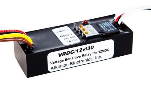
The only LVD that I found that could work is AtkinsonElectronics. They have many devices covering different voltages.

 
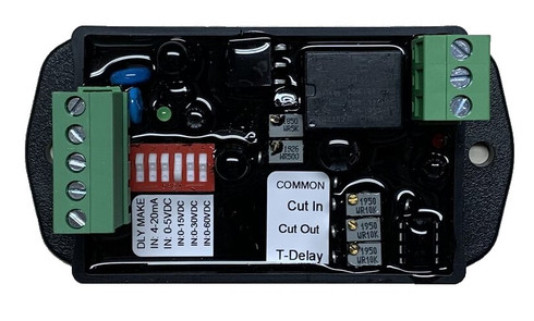
I've installed the VRDC SEL-X. It is the latest from Atkinson. I'm impressed. I tuned the cutoff voltage to be about 13.3V, cut in about 14.3V. The hold up time is 255 seconds. I haven't seen any LV battery disconnect with this many features and adjustments.

I have two 100 Watt Renogy solar panels, in series for 24V, running into a Victron Smartcontroller 15A. This feeds into a 12VDC 100AH Battleborn battery.

I put another, unconnected Battleborn in a 3/4" thick plywood box with 2" of Polyisocyanurate insulation. The bottom of the box has a 1in thick, 11in long x 7in aluminum heatsink. I added two PTC heaters in the center of the heatsink. The PTC's start cold at about 11 amps 12V. As they get warmer, they drop to about 5A at about 100F. This is for both PTC's in parallel pair (12V). There is a temperature controller set to heat the heatsink to 100F. The temperature logger T1 is on that bottom heatsink, the Temp logger T2 is on the top of the unconnected battleborn battery, taped to the top with insulation over the sensor.

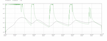
You can see the solar voltage come up in the morning and heat the T1 (green trace) on the heatsink. The temperature rises quickly, with moderation of the VRDC turning on, and dropping below 13.3V, holding for 255 seconds, then waiting for solar to charge past 14.3V. When the temperature was maintaining 100F, the connected battery BMS was inhibiting charge below 32F. During the later part of the day, the temperature warmed up and the BMS turned on. This started consuming the solar power for charging the battery which stopped the voltage from hitting 14.3V to turn on the heater.

If the battery fully charges again during the day, the BMS could shut off charging and let the voltage rise to 14.3V. This would heat the heatsink again.

The first long, 3 day cycle was not solar. It was a regulated voltage supply set at 14.4V, limited to 10.5A current. Solar diurnals were the next 4 cycles.

Note that both T1 and T2 were inside the insulated box. There was no ambient temperature sensor.

This is outdoors, in NH, under a covered shelter. I'll start a new cycle this week with T1 ambient air and T2 top of battery insulated.

You can see the days were warming up over the last 4 cycles. The heaters were on , raising the battery about 10F in temp. The last cycle was a warmer spring day. The connected battery BMS turned on earlier in the morning, stopping the heating of the unconnected battery.


20210327HeaterGraph2HeateronHeatsinkT1onHST2ontopBatteryinsulated.png

By using the VRDC, this is essentially a Solar Dump for Victron or any other controller without a dump option. The heaters will not discharge the battery. Essentially this is "found" energy that otherwise would have been lost.

I am totally relying on the BMS for inhibiting charging as necessary. I bought BattleBorn for this reason. I have disabled the Victron solar controller temperature inhibit to allow the supply of solar power at any temperature.
 
The bottom of the box has a 1in thick, 11in long x 7in aluminum heatsink.
I think adding a heat sink is a great idea. I've been struggling with limiting the amount of heat, as my heating pads are in direct contact with my aluminum compression plates. If I were to add a thick (maybe 1/4") sheet of aluminum under the cells, along with thin sheet of something less conductive (silicone mat?) between the heatsink and the compression plates, I could probably heat at a much higher rate without risking a large temp differential between my top and bottom cells.
By using the VRDC, this is essentially a Solar Dump for Victron or any other controller without a dump option. The heaters will not discharge the battery. Essentially this is "found" energy that otherwise would have been lost.
This is a really creative solution. I'm using cheep all-in-one inverters, so I don't have any dump load options. I'm thinking i might try to implement something similar using my ESP32-based 'system monitor'. Not for battery heating, but for generating hot water.

And nice work on the data logging. I'm finding that being able to log temps, voltages, current, etc is an absolutely essential part of testing and troubleshooting these systems.
 
Last edited:
  • Like
Reactions: Mia
I think adding a heat sink is a great idea. I've been struggling with limiting the amount of heat, as my heating pads are in direct contact with my aluminum compression plates. If I were to add a thick (maybe 1/4") sheet of aluminum under the cells, along with thin sheet of something less conductive (silicone mat?) between the heatsink and the compression plates, I could probably heat at a much higher rate without risking a large temp differential between my top and bottom cells.

This is a really creative solution. I'm using cheep an all-in-one inverters, so I don't have any dump load options. I'm thinking i might try to implement something similar using my ESP32-based 'system monitor'. Not for battery heating, but for generating hot water.

And nice work on the data logging. I'm finding that being able to log temps, voltages, current, etc is an absolutely essential part of testing and troubleshooting these systems.
My first heating attempt was more towards conduction (contact) instead of convection( air heating). My PTC heater is about 1.25" wide by 5.5" long aluminum. I was using 1/4" thick diamond aluminum plate. The heater was attached to the bottom of it with the temperature controller sensor. The conduction of heat was great through the plate, but less along the plate. (Thermal equations are related to the cross sectional area of metal conducting the heat). So, directly through the plate, I had about 6 square inches, but conducting the heat along the plate was less. I ended up with a hot spot contacting the bottom of the battery. Little heat was spread out to the aluminum plate edges. I tried adding air spaces and extra aluminum sheets, but this didn't help much.

I changed to a real heat sink extrusion. These are designed to conduct heat along the base of the extrusion and up each vertical fin. Then the air is heated by convection. Now I am heating the air in the box, not directly contacting the battery. This is a slower method of heating the battery, but is more even. I don't want to fry my new batteries... I can drive the temperatures higher to conduct more heat. Currently I limited the temperature to 100F. BattleBorn max temps are about 130F. I will increase the heatsink temperature as I develop this. That will safely increase the heating rate.

There are two solar dump features that I want. The first was heating the batteries in cold weather (little solar power). The second will be dehumidification in the summer (excess solar power). I will need to prove my first concept before I buy LiFePO4's for my camp in the Adirondacks. I have an outback solar controller that has the solar dump feature at my camp. I just haven't set it up yet. It only has excess solar in the winter when the LiFePO4 BMS's inhibit cold charging. I have lead acid deep cycles there now.

Note that this "solar dump" is a separate system. It doesn't involve Victron. It can be used in a truck camper with solar, alternator, grid charging, etc. I can go to camp at night and start the generator for power. I'll get power from the converter and the heaters will work. Later on, when the batteries heat up, I can use the batteries. If shut off the generator and go home, the system will work the next sunny day on solar.

If your using prismatic cells, you may want to insulate electrically. The cases could be connected to + or - potential.

You are right about logging and data collection. We all have perceptions, but data sometimes proves you wrong. The second thing to capture is the system inputs and setup. I've tried to add notes to describe. Sketches and pictures are better. I'll get to that.

My datalogger is a cheap one from Amazon. I have other temperature loggers, but they are harder to run/setup/power.


I've added the link to Amazon's cheap temperature controller, but I really like Akinson. It is a small engineering company that solves problems. The VRDC SEL was the latest product. They had the 12VDC VRDC, another 24VDC model, etc. They looked at all the different models and just added all the features to one.

You can set your cut out below the cut in, or invert them. You can use this for an auto generator start to turn on the generator when the volts goes low. You can work with AC power, 12V or 24V DC power. The sensing/switching can be 0-5V, 0-15V, 0-30V, 1-60VDC, and 0-20mA current. You can switch on/off up to 15 amps without a secondary relay. All of this is almost the same price as any one of the older models.

I tried some chinese High/Low voltage cutouts, but they used the same power as the control power. If you put 18Volts into the only input, trying to limit the high voltage, you smoked it. Atkinson has three separate inputs. 1 is the control power, it needs to be regulated to whatever you set it up for (24VAC, 24VDC, 12VDC...). You can put the higher voltages in the sensing input that isn't regulated. The common/NO/NC switch can be a different input/output.

 
Hey @diyernh that is some cool stuff! Even though I started this thread I seemed to have missed out on posts for the past month or so. So I have questions. ?

I'm a little confused on your circuit here. I get that you are triggering the VRDC based on the battery voltage getting down to 13.3V, and holding for 255 seconds. Is this just disconnecting the battery from the charge controller, but allowing the heater? I'm sorry if I'm being dense. I'm still on my first cup of coffee. ;)

I agree with @schroederjd that the 1" think aluminum "heat sink" is a great idea. That can really modulate the heat from the pads so as to not heat the cells too quickly. Where did you get the aluminum plate?
I'm mostly using the solar power. As the sun comes up, and the BMS is inhibiting charge, there is no battery. The voltage will rise to whatever you set your charger to. Mine is 14.4VDC on the Victron. With the VRDC cut in at 14.3, this will close the relay. The heaters will turn on, heating the heatsink. I had about 70W this morning. The heaters can take 120W if there it that much power. This extra power will come from the battery, or just solar if the battery is low and shutdown.

The VRDC will remain energized for 255 seconds after the input voltage (solar or battery) then shut off the heaters.

I picked 13.3VDC cutout by watching my BB batteries resting state. The LiFEPO4's have a constant voltage for a long time, but there is a quick drop at the full charge. I'm actually set at 13.27V. This shows up on the Victron sensor as Battery life remaining = 99%.

Yes, during low solar times, the solar will only trigger the 14.3 cut in, then use the battery until 13.3. This will happen over and over, heating a little at a time. This system is in parallel with the battery. Charge can go to the heaters, or charging the battery. The goal is to put power in the battery, but need to heat it first.

I've had the heatsinks in my barn junk. You can find scrap heatsinks from machine shops or scrap yards. It's one of those things made of Obtainum. I have made custom heatsinks for work out of aluminum and gang saws, or milling. I made some unique ones by drilling thousands of holes in a copper baseplate, cutting off copper rounds and soldering them in. Extrusions are usually 20ft from the aluminum companies. You may find cut sections.


Heatsinkusa.com has many extrusions, cut to your length. I haven't bought, just a google search find.

 
Last edited:
I'm mostly using the solar power. As the sun comes up, and the BMS is inhibiting charge, there is no battery.
I think this is part of what I'm confused by. My BMS has separate disconnects for charging and discharging; parallel but reversed polarity MOSFETs (kind of). So even when the charging is turned off (e.g. due to low temp), the discharging is still on. This means two things: (1) the charge controller still "sees" and is powered by the battery, and (2) a thermostat and heater can still be run off the battery. So if the battery is cold the charge controller will think it is pumping power to the battery but in fact will only be powering the heater, effectively supplementing or replacing the power the heater would be drawing from the battery. Once the BMS turns on the charge, most of the CC power is then going to charge the battery.

I see the value in having the VRDC to force what amounts to a duty cycle for the heating. Probably a good idea to prevent heating too fast, especially with the pretty hefty heaters you are using. I also see value in potentially using it for some other dump load, like water heating. Still, unless I'm missing something I don't think I would need it for heating the battery, unless I'm still missing something. I've now got lots of different heating pads that I'm experimenting with, and all are quite a bit lower power than yours, so I probably don't really need the duty cycling either.

By the way: There are lots of posts (videos, blogs, forums) about people supplementing batteries with supercapacitors to smooth out short, high C-rate power draws. I would guess there are some here on this forum, but haven't looked. The idea seems to draw almost religious fervor in arguing one side or the other, or at least it seems that way. At any rate, there is not much agreement about how well or poorly a supercapacitor will do.
I've looked at the super capacitors and decided not to go that way. I was concerned about the BMS turning on and discharging the caps at high C. That's not a good way to wake up on a cold morning.

You have the concept down in your first paragraph. My heaters are currently at 110F and the wattage is 50 watts. If the solar supplies more than 50W, then no battery energy is used. Less than 50W would discharge the battery. I'm tuning this cutout voltage to be the battery resting voltage. Currently I'm using 1% before the VRDC shuts off the heaters. If I continuously cycle the VRDC with insufficient wattage, the battery will settle below the cut out voltage (13.3) and not offer much duration. The voltage will drop and 255 seconds later, the heaters will be shut off. The battery will not be discharged below 99% full (13.3V). The VRDC is a Battery Protect Disconnect for the heater power.

The heaters are controlled with a heater controller. It cycles the heaters on/off. Currently on at 110F, off at 108F. Yes, the VRDC would also modulate, but on voltage available. You can see the temperature controller cycling on the graph. It maintains the temperature between 100F and 98 F. There is some hysteresis that it really goes about 97F to 102F. When it first start heating the cycles are slower. Heating for longer, cooling for longer. As the mass of the heatsink stabilizes near 100F, the cycles get a little quicker. If you look at the last day, the temperature controller never hit 100F. It was driving towards that, but the VRDC was turning on/off the voltage. This is longer, more uncontrolled temperature. I am using any power that I can salvage for heating. That last days heating (spikes around 70-90F) still added some heat.

Solar in the winter comes in waves. I will see many days with no sun, then days with sun. On the days were no solar charging happens, the VRDC will not be above the cut in volts. This could be days or weeks. On a sunny day, the sun will rise, maybe 5-10W of solar. The BMS is cold charging inhibited. The VRDC will turn on the heaters using a little of the battery then shut off. Minutes later, the sun is higher, and another pulse of solar/voltage/heat. This continues until the solar can run the heater alone (50W for me right now). For the rest of the sunny day, the heaters will work. Maybe the battery won't hit 32F that day, but then next day, it will be a little warmer. Maybe that second day the battery will warm up and the BMS will take a charge.

Others are using the battery power to continuously heat the batteries over the winter. I'm thinking that's inefficient as you will be having a higher temperature differential most of the time. More heat is lost when there is a higher temperature difference. I'm putting a larger heater to be able to heat the battery quicker. This is the usual energy conservation practice. Houses have boilers that can heat quickly rather than taking days. This means you can turn down the heat while you're gone to save fuel. When you come home and turn on the heat, it happens quickly.

There are other methods of energy conservation that uses power when it's cheap. Thermal stores are heated when there is excess power (low cost). The thermal store is heated to store heat until when it is needed.

Below is the temperature controller I have as recommended by another member.

 
Ok, thanks @diyernh. I think I get it now: You're only allowing the battery to be used for heating until it gets below your cutoff voltage. So if the battery is below your cutoff, there is no / insufficient solar, and it's cold, it will stay cold and you won't waste your remaining battery power on the heater.

In my planned system without a VRDC, I guess there is a risk - in the case of days of no sun - the heater will run down the battery until the BMS does a LVD. Then there's nothing to bring the batteries back up in temperature and voltage. That could mean they stay that way for the rest of the winter. So yeah, I see some real value to your approach.

The lucky part is that my system is at 9,000 ft in Colorado, and for the three winters we've had the system my logs indicate that there has only been a maximum of three days (for the season) when the solar was essentially not producing hardly anything, probably because of snow covering the panels. We get lots and lots of sunny days up there, even in winter. However, once the panels are free of snow, even on cloudy days the PV produces enough power that it has pulled our current AGM batteries back up to float.
 
For my 12v RV's Solar system, I currently do manual switching for the LFP battery heater. (When plugged in, the plugged-in Power Converter feeds the battery heater at all times, when it's under the minimum charging temperature). But I am beginning to think about an automation scheme: Depending on the Voltage of the PV array, I can disable heating completely at night (When PV Voltage is below 18 volts). When PV Voltage reaches about 24 Volts (it's using a "24V" relay coil,) it can enable the first of a pair of PV-to-SCC Relays. The second Relay is driven by temperature: In cold conditions, it routes output power from the first Relay, through a cheap PWM controller, into the heater pack. (There prorbably doesn't need to be any actual "battery pack" connected to the PWM controller, they simply run when power is present - and shut off when there isn't.) But another Relay (if 4-pin) or the second Relay itself (if 5-pin) routes PV power to the input "PV +" of a Solar Controller, only on the condition that the LFP battery pack has reached an acceptable temperature to charge the LFP battery pack (This is presumably an MPPT controller, connected to the LFP battery at all times.)

I am building this for only a tiny 12-Volt RV system, with about 430 watts of PV. I can use relatively small and cheap power relays. To go much above 40A, you would need to abandon the 5-pin "automotive type" (even if you wire them yourself) and switch to multiple 4-pin Relays, equipped with better power terminals and usable with higher current levels vastly higher current levels. But I think that the concept still works, and that also remains true if the battery bank voltage is 24 or even 48V.
 
Ok, thanks @diyernh. I think I get it now: You're only allowing the battery to be used for heating until it gets below your cutoff voltage. So if the battery is below your cutoff, there is no / insufficient solar, and it's cold, it will stay cold and you won't waste your remaining battery power on the heater.

In my planned system without a VRDC, I guess there is a risk - in the case of days of no sun - the heater will run down the battery until the BMS does a LVD. Then there's nothing to bring the batteries back up in temperature and voltage. That could mean they stay that way for the rest of the winter. So yeah, I see some real value to your approach.

The lucky part is that my system is at 9,000 ft in Colorado, and for the three winters we've had the system my logs indicate that there has only been a maximum of three days (for the season) when the solar was essentially not producing hardly anything, probably because of snow covering the panels. We get lots and lots of sunny days up there, even in winter. However, once the panels are free of snow, even on cloudy days the PV produces enough power that it has pulled our current AGM batteries back up to float.
I just installed solar this year. I'm north of Utica NY. Lots of fir and spruce trees. The sun stays below the trees for most of the winter. I'm giving this my best shot to work. There are still more options if this doesn't.

1616903388781.png
 
For my 12v RV's Solar system, I currently do manual switching for the LFP battery heater. (When plugged in, the plugged-in Power Converter feeds the battery heater at all times, when it's under the minimum charging temperature). But I am beginning to think about an automation scheme: Depending on the Voltage of the PV array, I can disable heating completely at night (When PV Voltage is below 18 volts). When PV Voltage reaches about 24 Volts (it's using a "24V" relay coil,) it can enable the first of a pair of PV-to-SCC Relays. The second Relay is driven by temperature: In cold conditions, it routes output power from the first Relay, through a cheap PWM controller, into the heater pack. (There prorbably doesn't need to be any actual "battery pack" connected to the PWM controller, they simply run when power is present - and shut off when there isn't.) But another Relay (if 4-pin) or the second Relay itself (if 5-pin) routes PV power to the input "PV +" of a Solar Controller, only on the condition that the LFP battery pack has reached an acceptable temperature to charge the LFP battery pack (This is presumably an MPPT controller, connected to the LFP battery at all times.)

I am building this for only a tiny 12-Volt RV system, with about 430 watts of PV. I can use relatively small and cheap power relays. To go much above 40A, you would need to abandon the 5-pin "automotive type" (even if you wire them yourself) and switch to multiple 4-pin Relays, equipped with better power terminals and usable with higher current levels vastly higher current levels. But I think that the concept still works, and that also remains true if the battery bank voltage is 24 or even 48V.
I racked my brain on trying to use the direct PV solar power to heat the batteries. The 24V is unregulated and can be about 48V max open circuit. My 24V relays, etc couldn't handle that much voltage. I tried a 24V to 12V converter, then found that couldn't handle the higher volts. I tried a High/Low voltage cutout like my VRDC, but smoked that. A PWM SCC can't be used with 24V panels on a 12 V battery. I'd have to use an MPPT SCC. That was just easier to use the regulated power output of the SCC. By using the charging voltage after the SCC, It automatically works when plugged into the generator. No need for separate heaters/circuits.
 
Back
Top