diy solar

diy solar

On Keeping LFP Warm

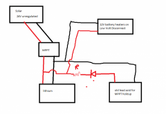
I racked my brain on trying to use the direct PV solar power to heat the batteries. The 24V is unregulated and can be about 48V max open circuit. My 24V relays, etc couldn't handle that much voltage. I tried a 24V to 12V converter, then found that couldn't handle the higher volts. I tried a High/Low voltage cutout like my VRDC, but smoked that. A PWM SCC can't be used with 24V panels on a 12 V battery. I'd have to use an MPPT SCC. That was just easier to use the regulated power output of the SCC. By using the charging voltage after the SCC, It automatically works when plugged into the generator. No need for separate heaters/circuits.
Racking my brain too. Direct-from-the-PV is definitely "too much" voltage for the "12v" heater pads I'm using. (When the charging day begins, I've got about 65V coming in from my wired-in-series panels.) Most 12v and 24v Replays can handle pretty high voltage on the switched "power legs" with no issues up to 60-80 volts. (My incoming PV power is switched, BTW.) Some can switch 250 volts. But somehow, an MPPT controller must be able to obtain a small amount of input "battery power" power from a battery which CAN be charged in low temperatures. So you would need *ANOTHER* MPPT, attached to a somewhat small AGM or other Lead-Acid battery. I'll describe this as a small AGM battery.

I'm proposing a lot more switches. The PV input goes directly to the new and "small" MPPT at all times, but it's output (into the AGM battery at all times) has another switched path - into the heater pad. This is only switched "on" when the LFP battery bank temp sensor shows low.
 
Last edited:
A relay with a "36 VDC coil" should be able to handle your maximum Open Circuit PV Voltage. (I've got a "24 volt" relay coil handling 36 volts for hours at a time, and I've never needed to replace that Relay). I will SWAG that you could ignore using the heater when you coil voltage (from the array) is significantly less than 36V, because the low Solar Array Voltage Voltage implies low power generation. (My own Solar provides virtually no power until the Voltage of the array exceeds 55 Volts). So the little MPPT is connected to the AGM battery and the Solar Array all the time. When the LFP temp is too low *and* the Array Voltage exceeds 36V, then output from the "little" MMPT is enabled to go through the heater circuit as well. (my motorcycle seat heaters are fairly low power and low current, they would not pull down the AGM voltage too far).

Then, when the LFP temp becomes adequate, PV input is also allowed into the main MPPT - the one charging the LFP battery bank. There might be a bit of "hunting" among the two MPPT controllers, but eventually the "little" MPPT is going to be satisfied, with its AGM battery fully charged.

You did say something which I find a bit curious - that PWM controllers can't connect between "higher voltage" PV arrays and "lower voltage" batteries. I thought that when MPPT controllers have 'no use' for extra power which the PV Array is offering, they will simply fall into PWM (rapidly disconnecting and re-connecting he panels), leaving unwanted power in the PV Array while disconnected. That way, they can present a very low average voltage to the batteries (e.g. 13.6 or even 13.4 Volts, in "float stage" when the AGM battery is filled). The maximum Array Voltage on my own MPPT SCC is rated at 150 Volts, and it can definitely fall into PWM to avoid giving "too much" power into the batteries when the batteries are charged.
The manufacturers don't really hold your hand to clearly state the input voltage to a PWM 12 Volt battery solar converter. Renogy shows the maximum volts input is 25VDC solar for their 12V Wanderer LI 30A PWM. I have the 100W Renogy solar panels with open circuit voltage as 22.3V. 2 in series would be 44.6V. That's beyond their specification. You may find a PWM controller that works. It's up to you to try it, or call the user support for your model. PWM really is just an on/off switch. You could be pulsing high voltage. That may be okay if you have a robust, high resistance load. If that big load goes away and you try PWM with a small electronic device (cell phone charger, light bulbs, etc, they will smoke. Running your 12V heaters could be a big enough load, but your taking a chance if the heating element blows


I tried using a 24V to 12V converter, but the specs showed that it needed regulated 24V, max 35V input.


I thought I could high limit out the voltage with a high voltage/low voltage cut off. Then feed that limited power into the 24 to 12V converter. I smoked it.


Maybe you could use a 24VDC MPPT that feeds into a 12VDC MPPT or a 24V to 12V converter.... Arghhhh???

This was running around in circles looking for a solution. I don't want to feed 44V into my camper when it's unattended. The 12V wiring is not rated for that. The fuses may not blow with high voltage and low amps. Adding more safety controls... It was beginning to be a mess. Many nights doing notes/ what if, then what analysis.

By using the 24VDC Solar, into a MPPT designed to charge 12V was by the book. Adding a low voltage disconnect to shut off loads is standard usage. You can have different low voltage disconnects for different loads. All that I did was find a very precise battery disconnect to shut off the heaters if the voltage drops lower than a fully charged battery.

I have other loads on low voltage disconnects like my 12V dehumidifier. That LVD is one of the the standard ones with only a couple settings.

I still like the Atkinson disconnect. You can disconnect the load by current too. A temperature snap switch and resistor could start/stop the current to turn it into a Low Temperature Disconnect, or High Temperature Disconnect.

 
Racking my brain too. Direct-from-the-PV is definitely "too much" voltage for the "12v" heater pads I'm using. (When the charging day begins, I've got about 65V coming in from my wired-in-series panels.) Most 12v and 24v Replays can handle pretty high voltage on the switched "power legs" with no issues up to 60-80 volts. (My incoming PV power is switched, BTW.) Some can switch 250 volts. But somehow, an MPPT controller must be able to obtain a small amount of input "battery power" power from a battery which CAN be charged in low temperatures. So you would need *ANOTHER* MPPT, attached to a somewhat small AGM or other Lead-Acid battery. I'll describe this as a small AGM battery.

I'm proposing a lot more switches. The PV input goes directly to the new and "small" MPPT at all times, but it's output (into the AGM battery at all times) has another switched path - into the heater pad. This is only switched "on" when the LFP battery bank temp sensor shows low.
The warnings in the MPPT manuals were one of my first worries. "Don't disconnect the battery without disconnecting the solar first". Then they say to install a LiFePO4 battery that the BMS will disconnect if it's full or low voltage. This is one of those sales points that they sell you something that can't be used!.

I called BattleBorn which works with Victron. I went on the Victron community page. Both Battleborn and Victron said that MPPT controller will work without a battery connected. I bought a Victron MPPT Smart controller and 2 BattleBorn batteries. I've seen this to be true in my testing that a battery is not needed to run the Victron.

My camp has an outback 60A MPPT. I haven't tried that yet. During my talk with BattleBorn they mentioned adding a parallel deep cycle battery if the MPPT controller needs it. We talked it over for a while and thought the best solution would be to add resistance to the lead acid battery. Charging the lead acid with a LiFePO4 charging profile could damage the lead acid. Too high voltage, current, ect. By adding a large resistor, you would moderate charging and discharging voltages are current. The MPPT may only need a few volts/ watts to wake up.

One other cheap option for battery power would be one of those small 12V car dashboard solar panels on the battery side. If the sun hits that, it could show 12V when the BMS has disconnected the battery. You may need to solder a diode into the cheap dashboard panel wire. Most of them recommend disconnecting when you start the engine. They have cheap diodes that short and let the power run backwards (discharging) at night.

I have not tried either hack yet. The Victron is pretty good at working with no battery connected.
 
The issue with a single MPPT is the pretty large difference in charge profile for the LFP and parallel lead-acid batteries. That's why charge I'm recommending a smaller and cheaper add-on solar controller, with its own battery. The heater circuit is attached to that battery, with both the 'only-in-low-temperature' and another "night-time-shutoff" device inline on the +12v supply line into the heater pad(s). That shutoff device could be the smallest of the Victron "battery-protect" devices, programmed all the way up to Mode-8 on the programming display. (12.0 Volts disconnect, 13.0 Volts reconnect.) That would pretty much assure that the heater pads are only run when the "smaller and cheaper" MPPT is providing at least "float mode" charge voltage into the battery -- which can only happen in the daytime. ;)

Whether a cheap PWM could handle that incoming voltage, with only a "small" lead-acid battery to handle the huge difference between connected and disconnected Voltage, is an open question, and the answer is probably "No". When an MPPT runs in PWM mode, it still has the "huge" inductor (be it electronic or physical) to smooth out the input side - and a basic PWM doesn't have that. But it sounds like you already have two MMPT controllers on hand - the Victron and the Outback. Why not dedicate the smaller to the new lead-acid battery and heater circuit? They can share the Solar input array - whether one is disconnected or not (internal to the MPPT) is an internal micro-decision of the Controller, and the desired battery output Voltage is a matter of your own programming.

We still have the problem of switching the path of "PV +" into the LFP-dedicated array, but I still make a SWAG that a Relay with 36-VDC coil, sitting right on the "PV +" input, would handle the 45-48 disconnect Voltage withouth problems.
- - -
Complex side note: In my travel trailer with LFP batteries, the "trailer battery charge" wire in the Bargman connector (from the tow vehicle) can run at either "under-the hood" operating voltage (typically 13.4 - 1.42 volts, depending on the state of the TV starter battery) - or at a regulated 36 volts, through a DC boost 12V -> 36V converter-regulator. This is under the control of a dashboard within the TV. Within the Trailer, and switching automatically, "PV +" is connected to the Tow Vehicle when the Voltage on that line exceeds approximately "24 Volts", and remains connected until Voltage on that wire drops below about 18V (the minimum "hold-in" Voltage of an activated "24 Volt" Relay coil). That 24-volt Relay is subjected to 36 volts and held in ALL THE TIME while I tow the Trailer with this Tow Vehicle - because the 430 watts being provided by the Tow Vehicle in "36 volt mode" is more than I get from the genuine panels, except near Solar Noon on a cloudless day.
- - -
But, now that I reconsider, you don't actually need a "36 volt" relay at all. Your "PV +" input from the panels is split into the two MPPT controllers, but the big one (for the LFP batteries) is only "enabled" when the main "thermostat relay" is NOT calling for heater activation. It doesn't matter if "PV +" is active into the LFP batteries when the temperature of the battery pack is good - even at night. It only matters that "PV +" into the LFP charger be disconnected when the battery pack is too cold.

The switched "power" Voltage can be zero, or 48 volts. (Or 'whatever', most of these Relays can handle more than 60 Volts of difference between "connected" and "disconnected". Some can handle more than 200 Volts). The COIL voltage need only be 12v abled/disabled from the thermostat relay output.
 
Last edited:
The issue with a single MPPT is the pretty large difference in charge profile for the LFP and parallel lead-acid batteries. That's why charge I'm recommending a smaller and cheaper add-on solar controller, with its own battery. The heater circuit is attached to that battery, with both the 'only-in-low-temperature' and another "night-time-shutoff" device inline on the +12v supply line into the heater pad(s). That shutoff device could be the smallest of the Victron "battery-protect" devices, programmed all the way up to Mode-8 on the programming display. (12.0 Volts disconnect, 13.0 Volts reconnect.) That would pretty much assure that the heater pads are only run when the "smaller and cheaper" MPPT is providing at least "float mode" charge voltage into the battery -- which can only happen in the daytime. ;)

Whether a cheap PWM could handle that incoming voltage, with only a "small" lead-acid battery to handle the huge difference between connected and disconnected Voltage, is an open question, and the answer is probably "No". When an MPPT runs in PWM mode, it still has the "huge" inductor (be it electronic or physical) to smooth out the input side - and a basic PWM doesn't have that. But it sounds like you already have two MMPT controllers on hand - the Victron and the Outback. Why not dedicate the smaller to the new lead-acid battery and heater circuit? They can share the Solar input array - whether one is disconnected or not (internal to the MPPT) is an internal micro-decision of the Controller, and the desired battery output Voltage is a matter of your own programming.

We still have the problem of switching the path of "PV +" into the LFP-dedicated array, but I still make a SWAG that a Relay with 36-VDC coil, sitting right on the "PV +" input, would handle the 45-48 disconnect Voltage withouth problems.
- - -
Complex side note: In my travel trailer with LFP batteries, the "trailer battery charge" wire in the Bargman connector (from the tow vehicle) can run at either "under-the hood" operating voltage (typically 13.4 - 1.42 volts, depending on the state of the TV starter battery) - or at a regulated 36 volts, through a DC boost 12V -> 36V converter-regulator. This is under the control of a dashboard within the TV. Within the Trailer, and switching automatically, "PV +" is connected to the Tow Vehicle when the Voltage on that line exceeds approximately "24 Volts", and remains connected until Voltage on that wire drops below about 18V (the minimum "hold-in" Voltage of an activated "24 Volt" Relay coil). That 24-volt Relay is subjected to 36 volts and held in ALL THE TIME while I tow the Trailer with this Tow Vehicle - because the 430 watts being provided by the Tow Vehicle in "36 volt mode" is more than I get from the genuine panels, except near Solar Noon on a cloudless day.
- - -
But, now that I reconsider, you don't actually need a "36 volt" relay at all. Your "PV +" input from the panels is split into the two MPPT controllers, but the big one (for the LFP batteries) is only "enabled" when the main "thermostat relay" is NOT calling for heater activation. It doesn't matter if "PV +" is active into the LFP batteries when the temperature of the battery pack is good - even at night. It only matters that "PV +" into the LFP charger be disconnected when the battery pack is too cold.

The switched "power" Voltage can be zero, or 48 volts. (Or 'whatever', most of these Relays can handle more than 60 Volts of difference between "connected" and "disconnected". Some can handle more than 200 Volts). The COIL voltage need only be 12v abled/disabled from the thermostat relay output.

I have two different solar installations. The photo of the pavilion and the 5th wheel is stationary on land north of Utica NY. I have 600W of solar (2S3P) for nominal 24Volts. That will use the outback SCC. Currently I have deep cycle lead acid commercial batteries (2 pairs of two 6VDC). They are about 8 years old and will need to be replaced. I'm looking at LiFePO4's for that camp, but need to work out all of the issues on heating batteries in the cold Adirondack winters (-30F record low, but does hit -15F often). The sun angles are low, trees in the way. I'm guessing I will get 3-4 hours per day in late December. Maybe about 10% of the 600W power (60W). The system may just shut down for a few months as the solar can't heat the batteries enough. Later in February, it will probably starts heating enough and charging as the sun gets stronger. That camp is about 5 hours away from me. I'm building boxes and testing ideas at my house in NH.

In NH I have the Victron, 2 BattleBorns, etc. I'm fixing up my Lance truck camper with solar. If I can't get one BattleBorn heated with two 100W solar panels in series, it would be worse in the Adirondacks with less sun.

I'm only running one solar array (24V), one SCC, and one set of 12V batteries for each spot. The MPPT's will pull the maximum power out of the panels. Dropping to PWM will lose power that I don't have much of. Maybe you're in a warmer area with more sun? I'll need all my solar to heat the batteries. Once they are warm, I'll need all my solar to charge the batteries and run some appliances that I need.

I don't know your power needs, but if you can disconnect the loads from your Lithium batteries with low voltage, or low temperature, you should be able to stop all power from draining out of your batteries. I don't know what your MPPT SCC takes for constant power. Mine is much less than 3 watts (.25A at 12V). 200AH of batteries would run for a month without any solar input before the BMS shuts down due to low battery. Then you could have issues if the MPPT can't wakeup without a battery.

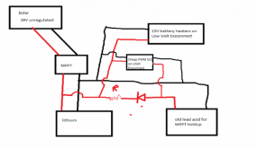
Simple solutions could be to add a lead acid to the MPPT SCC in parallel to the Lithiums. Add a diode so it can only discharge. Add a resistor so it won't discharge quickly, just need a few watts out of it. When the Lithiums disconnect from low voltage, the lead acid would only have a small draw. It would run until its totally dead. That's bad for lead acid, but this could be a discarded battery that already was degraded. You could use a dashboard solar panel for charging the lead acid, or manually charge it when you are able to, or add a cheap MPPT 12VDC - 12VDC lead acid charger from the lithiums. That would charge the lead acid when you have power, and the diode/resistor would slowly discharge to hold up the MPPT power.

1617067656329.png

If all fails with solar / MPPT / Lithium batteries. I could run an auto-start generator for camp. That's another project though.

Working all in 12Volts is a lot easier. If I can't get this to work, I'll stay with lead acid batteries at my camp in the Adirondacks. No heating of the batteries, no sudden disconnects of the batteries. Bad part is less output and life than Lithium batteries.

Rereading your note, ... "It only matters that "PV +" into the LFP charger be disconnected when the battery pack is too cold.". I gave up on that. There is no way I can inhibit the battery from taking a charge when it's too cold. There are BMS's inside the batteries that sense the internal battery temperature. I bought BattleBorn and one Big Battery LiFePO4's. They tested perfectly at shutting off charging below freezing. They will not start charging until above freezing. I trust BattleBorn for temperature sensing after Will cut one apart. The sensor wire is on a cell. Will proved that the BigBattery BMS temperature sensor is not on the battery cell, but is hanging in the air.

I disabled temperature charging limits on my SCC. It will charge at any temperature. BattleBorn should protect with the BMS.


SCC's come with battery temperature sensors that mount on the positive battery post. This is NOT the temperature of the cells inside the battery. The battery terminals is just a post with wires on the other side. I discussed this with BattleBorn and insulated the top of the battery and posts. This makes the temperature rise through the battery inside to get to the temperature sensors on the post.
 
Last edited:
Now understood, thanks. Your simple solution looks pretty good, with the resistor sized to take out some of the 'excess' charging Voltage which would tend to overcharge the old lead-acid battery.
 
Now understood, thanks. Your simple solution looks pretty good, with the resistor sized to take out some of the 'excess' charging Voltage which would tend to overcharge the old lead-acid battery.
Actually the diode on the positive shows only power leaving the positive. You can't charge the battery by feeding the charge backwards on the positive cable. The battery, as shown will only discharge. If I bought a diode for this, I would buy a package that can be used in your solar panels as spares Solar panels have diodes to avoid backfeeding your battery charge through the solar panel at night, trying to heat the sky. Sometimes they short out.

The resistor is only to slow down the lead acid current draw. The LiFePO4 batteries will supply full current to any load. The resistor will drop the lead acid voltage and current to be minor. Once the BMS shuts down the LiFePO4 batteries, the only power supplied would be the lead acid. If you have a very small load (MPPT SCC power), it will supply reasonable voltage, small current, until the battery is dead.


You would need to charge the lead acid before the diode and resistor. ie throwing a cheap 12V PWM SCC fed from the higher MPPT/Lithium battery like below.

I'm planning to run without the lead acid and PWM SCC. If it works, great, if it doesn't, then I could add the cost and complexity. Note that the PWM SCC should be on a Low voltage disconnect, only charging the lead acid when the MPPT/Lithium are higher voltage. I could picture the battery trying to charge its self in a perpetual heat loss if the PWM SCC doesn't cut out.

The Atkinson VRDC low voltage disconnect allows any cut-in or cut-out voltage. It can cut out at 13.8V and cut in at 14.3V. The only thing they want is the cut-in and cut-out to be about 1/4V away from each other. This is the way I'm trying not to use any battery power. The only place the solar MPPT power will go when the BMS inhibits the battery charging will be the heaters. At any time the battery is warm enough, it will grab the MPPT SCC power for charging.


1617146267624.png
 
I'm sure you have already considered this, but it needs to be said out loud by somebody, so I'll be the one to say it. Usually when it's that cold you have the heater running. Something as simple as a small duct into the battery area would keep the batteries warm, no? I've also seen times where people locate the batteries near the water heater, or the inverter. That way there's always a little bit of heat in the immediate vicinity. Just a thought
This was my thought also (a camper battery, so not a regular issue), but since our battery is outside in a battery box, the idea doesn't work. Maybe we'll do something different next year if it looks like this "too close to winder travel" looks likely. I also thought we could bring the battery inside, but the furnace needs to be connected to work. Also thought to just disconnect the charge line from the tow vehicle, but that, I guess, disconnects the trailer brakes. So far, my ideas aren't going very far.
 
I'm afraid I am really looking for a simple method for those few nights camping that might get down to freezing without buying the expensive Battleborn heater. We just got the LifePo4 battery and hadn't really been planning winter time camping. I've thought to insulate with some foil hot/cold bags that are used for food and an USB pet bed type heater but I don't know how to set it up. I'm concerned about putting the heating pad on the battery itself, but not sure what to use between it and the battery without losing all the heat. It seems like most systems put the heater under the battery - again, what do you put between the battery and the pad? We have a small bit of space in the battery box, but not much. Any thought on this simple method?
 
I'm afraid I am really looking for a simple method for those few nights camping that might get down to freezing without buying the expensive Battleborn heater. We just got the LifePo4 battery and hadn't really been planning winter time camping. I've thought to insulate with some foil hot/cold bags that are used for food and an USB pet bed type heater but I don't know how to set it up. I'm concerned about putting the heating pad on the battery itself, but not sure what to use between it and the battery without losing all the heat. It seems like most systems put the heater under the battery - again, what do you put between the battery and the pad? We have a small bit of space in the battery box, but not much. Any thought on this simple method?
Just "getting down to freezing" shouldn't be a problem for most batteries. For a Battle Born, it would take a long time to have the cold sink to the internals. It's a plastic case, sealed. The cold would need to transfer through the case, then some air and plastic to get to the battery cells.

The amount of heat transferred is related to the difference in temperatures. ie if the battery is 40F and the air is 30F, you have a temperature difference (dT) of 10 degrees F. This will slowly cool the battery and will take a long time to get the inside battery cells colder than 32. I'd guess it would be greater than 12 hours. If it's above freezing the next day, it will probably never freeze. -20F temperature outside with a 40F battery is dT=60. The battery will freeze in an hour or so.

Much of the heaters discussed is for really cold locations for a long time. I could see -15F for a week or so. That needs heat to be able to charge.

I did talk to the Battle Born Tech support a while back. They allow charging at something like 35F, but will continue charging until it hits 25F. Once its cold, it would need to heat up past 35F to start charging again.

If you have Battle Born batteries, I would totally trust their internal BMS to stop charging when it's too cold. The battery will still put out power when its really cold. I would run them without worrying about the temps. If you do hit extreme cold temps, the BMS will not allow charging, but the battery will still work. Worst case is that the battery voltage drops and the BMS shuts it off. At that point, you will not have power. Then you can remove the battery and heat it by some manner and charge it up. You would have found the limit of the batteries. If you never have a problem, then you don't need to worry about heating.

I wouldn't worry about it if it was Battleborn but it's not. They tell me that the BMS will prevent charging if it gets below 32 degrees and also then allow charging when it warms up. My concern, actually, is having it get too cold overnight in the mountains (Outside overnight temps of 30 degrees for a few hours is not uncommon) and then needing to leave immediately when the tow vehicle automatically sends charging power through the charge line. Otherwise we just charge with solar later in the day as needed.

I'm very unclear about whether they are talking about battery temperature (which I have no way of measuring or outside temperature). If it's that cold, the battery will be working to run the fan for the furnace. I don't know if that's enough to keep it from being too cold to charge safely. I think I will just need to trust that the BMS will do what it's supposed to do.

Thank you

The issue is the temperatures inside the LiFePO4 batteries. If they are cold, the battery sort of plates itself with the metals when charging, essentially shorting out some, or all of that cell.

Will Prowse, the owner of this site and many YouTube videos, has frozen batteries and tried charging them. He then tore them apart to see how they work. Many of them allowed charging when cold. Some didn't even have any circuitry to sense the temperature. That could be intentional for some battery makers. If they don't have a Brand and can relabel their batteries, they can sell new batteries to people after they are shorted from cold weather charging.

You could search this forum for your battery brand, or search Will's YouTube videos. He's done most of the popular batteries.

On a sealed purchased battery, you will not know the internal temperature of the cells. You could tear it apart and add a sensor, but that will void the battery warranty. Another option is trying to understand the transfer of heat from the air to battery case, to the inside cells. There are people trying to guess. Maybe you could pour a little water into a thicker tupperware container and place it inside your battery box. If you shake the container on a cold day and the water froze, then there could be a chance that the battery could be frozen. Sort of a canary in a coal mine idea. A few ounces of water in a sealed tub should freeze way sooner than a thicker battery case with about 20 pounds of cells inside.

It's just as difficult to freeze the battery cells as it is to heat them when they are cold. I'm using 120F heat exchanger to warm the battery that is about 20F. That takes hours to heat the insides. That a dT of 100 degrees F. If you're seeing 30F air, you only have a dT of 2 degrees F. Not much cold will be transfers with just 2 degrees difference.

LiFePO4 batteries don't outgass like lead acids ones. Many people install them in the heated areas of the camper. That could keep them warm.

I was wrapped up trying to figure out how I could avoid charging when the battery was too cold. Charging could happen with Solar, Tow Vehicle, or Generator. That's a complex design trying to figure out what the inside cell temp is, then only block electricity from charging the battery, but allowing the battery to power the camper. I gave up also. Use the batteries and hope the BMS avoids charging them frozen.

There are others that have proven that the batteries do generate internal heating when being discharged. There's a chance that your morning usage could heat it a bit.

I wouldn't worry about freezing the batteries until you worry about freezing the water pipes in the camper.
 
I'm mostly using the solar power. As the sun comes up, and the BMS is inhibiting charge, there is no battery. The voltage will rise to whatever you set your charger to. Mine is 14.4VDC on the Victron. With the VRDC cut in at 14.3, this will close the relay. The heaters will turn on, heating the heatsink. I had about 70W this morning. The heaters can take 120W if there it that much power. This extra power will come from the battery, or just solar if the battery is low and shutdown.

The VRDC will remain energized for 255 seconds after the input voltage (solar or battery) then shut off the heaters.

I picked 13.3VDC cutout by watching my BB batteries resting state. The LiFEPO4's have a constant voltage for a long time, but there is a quick drop at the full charge. I'm actually set at 13.27V. This shows up on the Victron sensor as Battery life remaining = 99%.

Yes, during low solar times, the solar will only trigger the 14.3 cut in, then use the battery until 13.3. This will happen over and over, heating a little at a time. This system is in parallel with the battery. Charge can go to the heaters, or charging the battery. The goal is to put power in the battery, but need to heat it first.

I've had the heatsinks in my barn junk. You can find scrap heatsinks from machine shops or scrap yards. It's one of those things made of Obtainum. I have made custom heatsinks for work out of aluminum and gang saws, or milling. I made some unique ones by drilling thousands of holes in a copper baseplate, cutting off copper rounds and soldering them in. Extrusions are usually 20ft from the aluminum companies. You may find cut sections.


Heatsinkusa.com has many extrusions, cut to your length. I haven't bought, just a google search find.

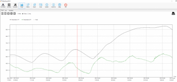
Adding my last data collection chart.

This is still one 100AH Battle Born battery, inside the wooden crate, the higher temperature is the top of the battery, with the entire top of the battery covered with insulation. The lower temperature is the ambient air in my cover-it shelter, exposed to air, no sun.

The heat is set at 120F on the extruded heatsink, on the bottom of the battery. There are 2 PTC heaters that heat this up quickly. These heaters were solar powered, just using solar power without using much battery power. ie the battery was charged, or low temperature inhibited.

You can see from the first part of the chart that I could only heat the battery (top insulated sensor) about 20F higher than the outside ambient temp. This would be enough for me. When I actually install this, I'll insulate better. 20F rise could get the batteries charging at about 12F. This may happen on a warm sunny days in January. Other days when it's cloudy/snowy, there will be no solar, no heating, no battery charging which will be just storing the batteries until the next sunny days.

The last part of the chart shows about 2 days of me running a generator and a controlled power supply to feed the heaters 24/7. At the later part of it, the system hit steady state. The heat was being lost at the same rate as it was being added. The battery top temperature leveled out and started dropping/rising a little due to the daily ambient temps. This shows the maximum that I could heat the battery above ambient with my heaters and insulated box. It's about 40F higher than ambient. I just wanted to know how hot it would get if the heaters were left on. That's hard to do with solar. It's dark more than light during the winter.

This chart shows how fast you can heat a BB Battery with 120F heat. This could be interpreted to see how fast you will freeze a battery with cold temperatures. You would need really cold ambient to get the battery temperature freezing, and it would take about 6-8 hours before the cold weather froze the battery cells. Wind or air movement would accelerate cooling.


1618674814065.png
 
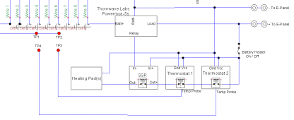
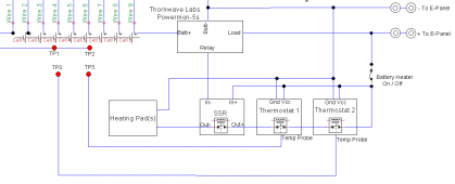
Although it took me a while to understand @diyernh and how he was using the VRDC SEL-X, I finally got it and liked the idea. I've come up with a variation that I think addresses the same issues as well as several others. Let's see if I can describe my idea. I haven't built it, but am experimenting with the components. Here's a subset of the schematic I've come up with:

Capture.PNG
I've not ordered the cells yet, as I watch the threads about the chaos of shipping from China right now. Assume they will be in the EVE / Lishen 280 / 272Ah class. They will be configured in two rows of 4, like 2 4S batteries side-by-side. This turns out to be somewhat square shaped pack when looking down from the top.

The "TP" items are temperature probes. The TP1 and TP2 are probes from my Overkill 8S 100A BMS. Here's what the components are, and what they do:
  1. The heating pads are silicone 12V, 12W pads with a maximum temperature of 60°C. The are sitting on silicone kitchen pads (trivets) on the bottom of the battery box. The will be attached to the bottom of an aluminum sheet that the cells sit on. I'll either have two of these pads connected in series (for 24V), or two sets of 2 pads. To be determined.
  2. Thermostat 1 is a 24VDC thermostat, that would turn ON when the temperature gets below some "heat required" set-point. For demonstration purposes, let's assume it turns on at 40°F (or below), and turns back off at 55°F. So this thermostat is the one that handles turning on the heating pads when the cells seem to be getting too cold. The probe for his thermostat (TP3) will probably be taped to the top of the pack, probably near the middle.
  3. Thermostat 2 is also a 24VDC thermostat, whose purpose is to manage / prevent the cells heating up too fast. This thermostat will turn on at something like 70°F or below, and will turn off at 90°F or above. The probe (TP4) will be around one-third of the way up the side of the pack, so closer to the bottom. This thermostat's job is to turn off the heat if the bottom of the cells (closest to the heat pads) warms up too fast. It would then turn on again if the bottom one-third of the cells is cool enough to continue heating.
  4. The Thornwave powermon-5s is a smart shunt much like the Victron smart shunt, but with some extra features. For the purposes of this discussion, the main thing is that it has a relay control output, and you can program this relay control via Bluetooth and an iOS or Android app for a number of different purposes. In this case, I would set it up to turn on a cheap SSR whenever the voltage is above a certain level, and turn it off below some other level. The purpose would be to not allow the heating elements if the battery voltage is below some level. In a normal daily cycle the solar charge controller (SCC) would present a high enough voltage that the heating would be enabled. But in the even that the panels are covered with snow or something for a number of days, this relay control would prevent running down the battery. Credit @diyernh for this idea, which is where he used the VRDC instead.
  5. Finally, the Overkill BMS shuts off charging if the temperatures (probes TP1 and TP2) gets down to 1°C or below. This will be the failsafe, in case there is no sun for several days or some other failure prevents the heating of the cells.
Basically, powering the heating pads requires thermostat 1, thermostat 2, and the SSR to be turned on. This means that in order for the heating to happen, the cell temperature needs to be a 40°F or lower, AND the lower part of the pack is at or below 90°F, AND the voltage from the battery and/or charge controller is above some level.

I think this setup addresses the following:
  1. Don't use battery energy to heat the battery unless it is well charged. Use SCC power if it is present.
  2. If the pack gets below 40°F, turn on the heat.
  3. If the pack needs heat but the bottom of the cells (near the heating element) gets too warm, turn off the heating elements until the warmth conducts up through the rest of the cells. In practice, this may cycle the heating elements on and off at some duty cycle, warming the cells but not warming them too quickly.
  4. If all else fails, the BMS will prevent charging the pack at or below 1°C.
Any thoughts?
 

Attachments

  • Capture.PNG
    Capture.PNG
    19.3 KB · Views: 7
Although it took me a while to understand @diyernh and how he was using the VRDC SEL-X, I finally got it and liked the idea. I've come up with a variation that I think addresses the same issues as well as several others. Let's see if I can describe my idea. I haven't built it, but am experimenting with the components. Here's a subset of the schematic I've come up with:

View attachment 47070
I've not ordered the cells yet, as I watch the threads about the chaos of shipping from China right now. Assume they will be in the EVE / Lishen 280 / 272Ah class. They will be configured in two rows of 4, like 2 4S batteries side-by-side. This turns out to be somewhat square shaped pack when looking down from the top.

The "TP" items are temperature probes. The TP1 and TP2 are probes from my Overkill 8S 100A BMS. Here's what the components are, and what they do:
  1. The heating pads are silicone 12V, 12W pads with a maximum temperature of 60°C. The are sitting on silicone kitchen pads (trivets) on the bottom of the battery box. The will be attached to the bottom of an aluminum sheet that the cells sit on. I'll either have two of these pads connected in series (for 24V), or two sets of 2 pads. To be determined.
  2. Thermostat 1 is a 24VDC thermostat, that would turn ON when the temperature gets below some "heat required" set-point. For demonstration purposes, let's assume it turns on at 40°F (or below), and turns back off at 55°F. So this thermostat is the one that handles turning on the heating pads when the cells seem to be getting too cold. The probe for his thermostat (TP3) will probably be taped to the top of the pack, probably near the middle.
  3. Thermostat 2 is also a 24VDC thermostat, whose purpose is to manage / prevent the cells heating up too fast. This thermostat will turn on at something like 70°F or below, and will turn off at 90°F or above. The probe (TP4) will be around one-third of the way up the side of the pack, so closer to the bottom. This thermostat's job is to turn off the heat if the bottom of the cells (closest to the heat pads) warms up too fast. It would then turn on again if the bottom one-third of the cells is cool enough to continue heating.
  4. The Thornwave powermon-5s is a smart shunt much like the Victron smart shunt, but with some extra features. For the purposes of this discussion, the main thing is that it has a relay control output, and you can program this relay control via Bluetooth and an iOS or Android app for a number of different purposes. In this case, I would set it up to turn on a cheap SSR whenever the voltage is above a certain level, and turn it off below some other level. The purpose would be to not allow the heating elements if the battery voltage is below some level. In a normal daily cycle the solar charge controller (SCC) would present a high enough voltage that the heating would be enabled. But in the even that the panels are covered with snow or something for a number of days, this relay control would prevent running down the battery. Credit @diyernh for this idea, which is where he used the VRDC instead.
  5. Finally, the Overkill BMS shuts off charging if the temperatures (probes TP1 and TP2) gets down to 1°C or below. This will be the failsafe, in case there is no sun for several days or some other failure prevents the heating of the cells.
Basically, powering the heating pads requires thermostat 1, thermostat 2, and the SSR to be turned on. This means that in order for the heating to happen, the cell temperature needs to be a 40°F or lower, AND the lower part of the pack is at or below 90°F, AND the voltage from the battery and/or charge controller is above some level.

I think this setup addresses the following:
  1. Don't use battery energy to heat the battery unless it is well charged. Use SCC power if it is present.
  2. If the pack gets below 40°F, turn on the heat.
  3. If the pack needs heat but the bottom of the cells (near the heating element) gets too warm, turn off the heating elements until the warmth conducts up through the rest of the cells. In practice, this may cycle the heating elements on and off at some duty cycle, warming the cells but not warming them too quickly.
  4. If all else fails, the BMS will prevent charging the pack at or below 1°C.
Any thoughts?
The Powermon looks like it will do everything and more. Report back on it when you try it out. The manuals don't really say how close you can set the Low Voltage cutout and the LV reconnect. My VRDC needed 1/4 Volt difference to work. It would be nice if you could program .1 volts more easily than potentiometers.

It would be good to see if the Powermon keeps all of its settings if the BMS shuts off the battery output. The manual says it loses the time/date and passwords, but doesn't mention other settings. It's hard to get details without going ahead and buying one.

I have BattleBorn batteries that I don't need to worry about the case being grounded or hot voltage. If you are using metal cased prismatic cells, you may want a electrical insulating pad to avoid shorting the cases to the aluminum sheet.

By the time we get all this previously lost power used, Victron will probably come up with a networked Solar Dump device. My Outback SCC does have that feature. I haven't looked at that yet for my 5th wheel in the Adirondacks.

I like the old fashioned Bimetal snap switches as a over heat protection. Digital electronics are convenient, but adding a overheat snap switch would protect from a runaway heating situation. I doubt you could ever overheat with the lower heating wattage/larger battery mass though.
 
The Powermon looks like it will do everything and more. Report back on it when you try it out. The manuals don't really say how close you can set the Low Voltage cutout and the LV reconnect. My VRDC needed 1/4 Volt difference to work. It would be nice if you could program .1 volts more easily than potentiometers.
Yeah, my hope is that the digital settings in the app are better than tweaking the pot in the VRDC, but that's all subject to how accurate the powermon is.

It would be good to see if the Powermon keeps all of its settings if the BMS shuts off the battery output. The manual says it loses the time/date and passwords, but doesn't mention other settings.
Yeah, that's my only worry. I did call the little company, and I think the designer / owner answered the phone and dealt with my questions. I forgot to ask about the power-loss. Now that I'm an official customer, I won't feel bad about calling back. I'll post here with the answers.

I like the old fashioned Bimetal snap switches as a over heat protection. Digital electronics are convenient, but adding a overheat snap switch would protect from a runaway heating situation. I doubt you could ever overheat with the lower heating wattage/larger battery mass though.
It's funny how different people feel comfort in analog vs digital and vice versa. Counting on bimetal to save my batteries from burning up makes me shake. As a digital electronics EE, it's kinda like when I first met an RF engineer where we had to interface. He tried to explain, and then just said "you digital guys need to understand that at some frequency it's just magic and you need to let it go and get out of the way."
 
  1. The heating pads are silicone 12V, 12W pads with a maximum temperature of 60°C. The are sitting on silicone kitchen pads (trivets) on the bottom of the battery box. The will be attached to the bottom of an aluminum sheet that the cells sit on. I'll either have two of these pads connected in series (for 24V), or two sets of 2 pads. To be determined.
Any thoughts?
I see many 12v silicone heat pads that seem to have a temperature sensor imbedded. Is this the type you are using? I am curious if that included sensor could be compatible with the thermostatic switch. Wondering if these sensors are somewhat generic.

The plan looks great to me.
 
I see many 12v silicone heat pads that seem to have a temperature sensor imbedded. Is this the type you are using? I am curious if that included sensor could be compatible with the thermostatic switch. Wondering if these sensors are somewhat generic.

The plan looks great to me.
Thanks for the vote of confidence!

I am specifically using heating pads that DO NOT have their own sensor / thermostat imbedded. We don't ever really know where they come form or how they work. I just want a heating pad that heats when power is applied, and doesn't heat when power is turned off. The logic of turning on the heating pad is then up to the circuit I set up, not the one that the guy selling heating pads sets up.
 
Yeah, my hope is that the digital settings in the app are better than tweaking the pot in the VRDC, but that's all subject to how accurate the powermon is.


Yeah, that's my only worry. I did call the little company, and I think the designer / owner answered the phone and dealt with my questions. I forgot to ask about the power-loss. Now that I'm an official customer, I won't feel bad about calling back. I'll post here with the answers.


It's funny how different people feel comfort in analog vs digital and vice versa. Counting on bimetal to save my batteries from burning up makes me shake. As a digital electronics EE, it's kinda like when I first met an RF engineer where we had to interface. He tried to explain, and then just said "you digital guys need to understand that at some frequency it's just magic and you need to let it go and get out of the way."
Did you get a chance to look at/test the powermon? I'm looking to buy a few more Low Voltage Disconnects. I need one for my 12VDC dehumidfier, and another for my battery heater. I can hold off for a few more months before ordering.

Was it easy to program? Capable of very close voltages between cutout and cut in? Did it keep the settings after a power outage?

Thanks,
Carl
 
Back
Top