I think adding a heat sink is a great idea. I've been struggling with limiting the amount of heat, as my heating pads are in direct contact with my aluminum compression plates. If I were to add a thick (maybe 1/4") sheet of aluminum under the cells, along with thin sheet of something less conductive (silicone mat?) between the heatsink and the compression plates, I could probably heat at a much higher rate without risking a large temp differential between my top and bottom cells.
This is a really creative solution. I'm using cheep an all-in-one inverters, so I don't have any dump load options. I'm thinking i might try to implement something similar using my ESP32-based 'system monitor'. Not for battery heating, but for generating hot water.
And nice work on the data logging. I'm finding that being able to log temps, voltages, current, etc is an absolutely essential part of testing and troubleshooting these systems.
My first heating attempt was more towards conduction (contact) instead of convection( air heating). My PTC heater is about 1.25" wide by 5.5" long aluminum. I was using 1/4" thick diamond aluminum plate. The heater was attached to the bottom of it with the temperature controller sensor. The conduction of heat was great through the plate, but less along the plate. (Thermal equations are related to the cross sectional area of metal conducting the heat). So, directly through the plate, I had about 6 square inches, but conducting the heat along the plate was less. I ended up with a hot spot contacting the bottom of the battery. Little heat was spread out to the aluminum plate edges. I tried adding air spaces and extra aluminum sheets, but this didn't help much.
I changed to a real heat sink extrusion. These are designed to conduct heat along the base of the extrusion and up each vertical fin. Then the air is heated by convection. Now I am heating the air in the box, not directly contacting the battery. This is a slower method of heating the battery, but is more even. I don't want to fry my new batteries... I can drive the temperatures higher to conduct more heat. Currently I limited the temperature to 100F. BattleBorn max temps are about 130F. I will increase the heatsink temperature as I develop this. That will safely increase the heating rate.
There are two solar dump features that I want. The first was heating the batteries in cold weather (little solar power). The second will be dehumidification in the summer (excess solar power). I will need to prove my first concept before I buy LiFePO4's for my camp in the Adirondacks. I have an outback solar controller that has the solar dump feature at my camp. I just haven't set it up yet. It only has excess solar in the winter when the LiFePO4 BMS's inhibit cold charging. I have lead acid deep cycles there now.
Note that this "solar dump" is a separate system. It doesn't involve Victron. It can be used in a truck camper with solar, alternator, grid charging, etc. I can go to camp at night and start the generator for power. I'll get power from the converter and the heaters will work. Later on, when the batteries heat up, I can use the batteries. If shut off the generator and go home, the system will work the next sunny day on solar.
If your using prismatic cells, you may want to insulate electrically. The cases could be connected to + or - potential.
You are right about logging and data collection. We all have perceptions, but data sometimes proves you wrong. The second thing to capture is the system inputs and setup. I've tried to add notes to describe. Sketches and pictures are better. I'll get to that.
My datalogger is a cheap one from Amazon. I have other temperature loggers, but they are harder to run/setup/power.
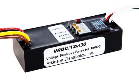
I've added the link to Amazon's cheap temperature controller, but I really like Akinson. It is a small engineering company that solves problems. The VRDC SEL was the latest product. They had the 12VDC VRDC, another 24VDC model, etc. They looked at all the different models and just added all the features to one.
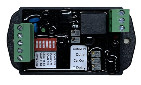
You can set your cut out below the cut in, or invert them. You can use this for an auto generator start to turn on the generator when the volts goes low. You can work with AC power, 12V or 24V DC power. The sensing/switching can be 0-5V, 0-15V, 0-30V, 1-60VDC, and 0-20mA current. You can switch on/off up to 15 amps without a secondary relay. All of this is almost the same price as any one of the older models.
I tried some chinese High/Low voltage cutouts, but they used the same power as the control power. If you put 18Volts into the only input, trying to limit the high voltage, you smoked it. Atkinson has three separate inputs. 1 is the control power, it needs to be regulated to whatever you set it up for (24VAC, 24VDC, 12VDC...). You can put the higher voltages in the sensing input that isn't regulated. The common/NO/NC switch can be a different input/output.
The VRDC is an adjustable DC Voltage Relay module that is designed for applications where a varying DC voltage is used to switch an adjustable relay, as in generator control, low battery voltage load disconnect, or over-charge load diversion. When used in generator control, the VRDC provides a...

atkinsonelectronics.com


")


