diy solar

diy solar

Off grid portable system for EV charging

Savagesymbiote86

New Member
Joined
Jul 25, 2021
Messages
3
Hi this is my first build to partially charge my PHEV.

PIP LV2424 MSD 24V 2.4kW, 120V Output, 2kW Solar Input 80A Mppt
RICH SOLAR 200 Watt 24 Volt Moncrystalline Solar Panel
2 12V 100Ah Solar AGM DEEP Cycle Battery
200amp Slo Blo fuse

I did the math & the draw is 1440watts, which should let me charge the car for 30mins & then charge the batteries & charge the car another 30mins at the end of the day. i do plan on getting another solar panel 2 12v 100Ah Li batteries in 3-4 months. The fuse is to connect to the batteries since they're AGM, was wondering what guage wires to use for connections.
 
I go to a voltage loss calculator like this and input my wire length and install low loss wire for less than 3%.
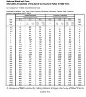
I then go to an ampacity chart like this and make sure the wires are rated for those amps. I also try to get it rated at my desired amps at 60C. Fuses protect wire, so the wire would be rated more than the fuse.
42FA169C-31F3-4297-8184-95D30EC204DD.jpeg
Finally, I’ll go to the oinverter manual to be sure I chose wire at least as thick as the recommendation.

Huge difference in wire size for a 2’ run compared to a 24’ run/
 
Last edited:
I like this wire gauge calculator

 
Will that fuse be good or should i have gotten a 275
Not everyone will agree with this, but based off ampacity of wire, I would not use that 275 amp fuse unless you had thicker than 4/0 wire, or the wire you are using is rated above 275 amps.

You want the fuse rated to blow before the wire. To me this also means whatever insulation that wire is rated to. If the 4/0 wire has 90C insulation and is rated for 260 amps, than if you exceed that amperage, the wires could get hotter. What happens when the current is above 260, I'm not sure. 90C is hot enough to burn you, so I'm sure the insulation does not hold up, and the copper may not melt, but not sure about the insulation. Fuses protecting the wire just does not mean the copper conductors melting, but also means the insulation not giving out and shorting somewhere.

So based off ampacity of wires and the chart I put in post #2, I would not use a 200 amp fuse unless the wire was 2/0 or greater. There are different charts that have different ampacities that show where wires with fewer strands are better than wires with more strands. You can also look on a manufacturers spec sheet and find perhaps the wire has teflon insulation of 105C.

IME, when my 12 volt inverter is at 1800 watts, because of 15% inefficiencies, it pulls 2100 watts from the battery, which comes to about 155 amps. I would expect a 2000 watt inverter at 24 volts to pull 85 amps when at max production. So in your instruction sheet, if the inverter says something along the lines of, "Not greater than 200 amp (TYPE of fuse like Class T or ANL) fuse," than a 200 amp fuse of could be used. You just need to make sure whatever wire you're using is rated for that, so as I read that chart, 2/0. If you wire with 2 gauge as some recommend for a 24 volt system, that wire has an ampacity of 130 amps at 90C, so I would put the fuse less than 130 amps. 130 amps also is more than I expect the inverter to pull.

I'm also not sure about a slow burn fuse. My two inverters call for a Class T fuse. For my 24 volt system, I am installing a class T fuse.
 
I ended up getting 4 awg guage wires & i just seen that they can carry a max of 150amps. I made a mistake with the 200amp fuse.
 
Back
Top