diy solar

diy solar

MPP LV6548 Ground/Neutral Safety?

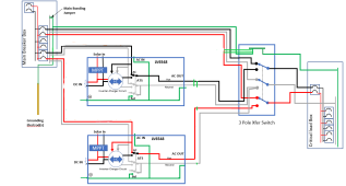
This is how I had planned to wire the units. I am almost certain that there will be current on the portion of the schematic you have marked. I am slowly coming to the conclusion that the field wiring of these units cannot fix this issue. I am hoping that the software will allow them to solve the problem internally. Without a definitive schematic directly from MPP it will take trial and error to figure this out.
I believe there will be current there also but there are some who think the objectionable current is caused by the extra ECGs so we need to determine what is correct.

It would be great if the new firmware had an option to not bond. It would be even better if the new firmware or some future firmware automatically did the bond on only one inverter when the inverters were paralleled.

With no firmware fix, the only solution seems to be to remove the bonding screw on all of the inverters except one. This is supposedly approved by MPP, but is it really? Will opening the inverter void the warranty? Will someone who is not all that comfortable with electricity and electronics to begin with want to do it? What if someone removes the wrong screw?

If you remove the screw on all inverters but one, ground fault clearing is now dependent on that one inverter. If you take that inverter out of your system and forget to replace the screw in one of the other inverters, you have no ground fault path in inverter mode. It might be better to remove all of the screws and use the neutral-ground bond in the main panel (or the subpanel if you don't have AC input). But that requires jumping the inverter's neutral input and output, which is not supported by MPP although they did not explain why.

As we have seen, it can be difficult to detect the objectionable current. How many people will be able to determine if their installation is safe or not?

Not an easy situation.
 
Last edited:
I believe there will be current there also but there are some who think the objectionable current is caused by the extra ECGs so we need to determine what is correct.
Not caused by, they are just the available path.
The inverters are the cause.
 
It would be great if the new firmware had an option to not bond. It would be even better if the new firmware or some future firmware automatically did the bond on only one inverter when the inverters were paralleled.

Will someone who is not all that comfortable with electricity and electronics to begin with want to do it?

I would assume if one is confident enough to assemble the system itself, 3 pole switch, etc.... than screw removal would be negligible. I understand these are different things though especially when considering the warranty "seal breakage" is concerned.
 
If you can defeat the neutral ground bonding, in all but one inverter. And, isolate the grid neutral from the inverted neutral. Then, there is no issue.
I think this is the real fix, whenever you have more than one inverter, remove the bonding screw from all but one. But I'd want assurance from MPP / vendor that this won't void the warranty.
 
I think this is the real fix, whenever you have more than one inverter, remove the bonding screw from all but one. But I'd want assurance from MPP / vendor that this won't void the warranty.
More than likely it will void the warranty, sadly.
 
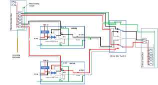
I mentioned in post 221 that jumping the input and output neutrals of the inverter is not supported by MPP, but it looks like they are connected anyway. They are definitely connected in bypass mode. They also appear to be connected in inverter mode via the EGCs and the bonding jumper in the main panel. The diagram below shows two inverters in inverter mode with only the top inverter bonding neutral to ground. The orange highlighted paths connect the inverter inputs to outputs if I am not mistaken.

1646675580195.png
 
Last edited:
It appears that these inverters were just designed wrong. I'm very surprised that this is the case.
It needs to be corrected at the factory level.
 
I mentioned in post 221 that jumping the input and output neutrals of the inverter is not supported by MPP, but it looks like they are connected anyway. They are definitely connected in bypass mode. They also appear to be connected in inverter mode via the EGCs and the bonding jumper in the main panel. The diagram below shows two inverters in inverter mode with only the top inverter bonding neutral to ground. The orange highlighted paths connect the inverter inputs to outputs if I am not mistaken.

View attachment 86433
I have been reading through all of this and pulling my hair out on my setup for a while now. I FINALLY had some time to go back and mess with mine because I still had current on my ground at the Main panel.

Here is what I ended up doing:

1. Ground from Main panel to:
Both my transfer switch as well as the disconnect I installed that feeds/isolates the inverters for any maintenance etc. that may be required. Then run this same ground directly to the Sub/Critical loads panel. Make sure the Neutral is NOT switched in the disconnect!! Or you will loose your bond from the main panel.

2. Removed the ground to the inverters. Only L1 and N to inverter 1, L2 and the (same) neutral to inverter 2. This means NO ground on the inputs OR the outputs.

3. Tested all points to make sure the inverter cases, disconnects etc. had 120v from hot to the chassis' (This proves they are grounded).

4. Cycled through normal and operation and transfer to battery (simulated power outage) modes.

5. Checked for current on the grounds at all points including the Main panel and they are now gone!!


I had been running a number of tests for quite a while and I believe what you posted above is correct. These inverters have a N/G bond on both the inputs and outputs which is creating the issues. This would be proper if you want to use them in an off grid only situation and don't have a need for charging from the Mains.
With that in mind these inverters also have the cases bonded to the neutral as well. To me the software update may fix the bonding, but it would have to do this through software (changing how the relays react). What happens if a relay fails? This is something to think about...
(The inverters now use the N/G bond from the Main panel the way I described doing this)

Let me know what you guys think!

Sorry it has taken me so long to report any findings but I've been taking care of my wife and it's been pretty exhausting.


Thanks!
Dan
 
Good to hear from you Dan. I hope your wife is recovering.

The next question is ground faults and if a breaker will trip. As you don't have a ground to the inverters, where are you bonding N-G?
 
Ground faults are good, when in battery mode. Maybe not, in bypass mode. (This is only referring to a fault, inside the inverters) N/G bond is at the main panel, as it should be. (That's how I understood it, anyway)
 
I have been reading through all of this and pulling my hair out on my setup for a while now. I FINALLY had some time to go back and mess with mine because I still had current on my ground at the Main panel.

Here is what I ended up doing:

1. Ground from Main panel to:
Both my transfer switch as well as the disconnect I installed that feeds/isolates the inverters for any maintenance etc. that may be required. Then run this same ground directly to the Sub/Critical loads panel. Make sure the Neutral is NOT switched in the disconnect!! Or you will loose your bond from the main panel.

2. Removed the ground to the inverters. Only L1 and N to inverter 1, L2 and the (same) neutral to inverter 2. This means NO ground on the inputs OR the outputs.

3. Tested all points to make sure the inverter cases, disconnects etc. had 120v from hot to the chassis' (This proves they are grounded).

4. Cycled through normal and operation and transfer to battery (simulated power outage) modes.

5. Checked for current on the grounds at all points including the Main panel and they are now gone!!


I had been running a number of tests for quite a while and I believe what you posted above is correct. These inverters have a N/G bond on both the inputs and outputs which is creating the issues. This would be proper if you want to use them in an off grid only situation and don't have a need for charging from the Mains.
With that in mind these inverters also have the cases bonded to the neutral as well. To me the software update may fix the bonding, but it would have to do this through software (changing how the relays react). What happens if a relay fails? This is something to think about...
(The inverters now use the N/G bond from the Main panel the way I described doing this)

Let me know what you guys think!

Sorry it has taken me so long to report any findings but I've been taking care of my wife and it's been pretty exhausting.


Thanks!
Dan

Hi Dan. Hope your wife is doing better. Is this what you did?

1646786722987.png
 
Looks like what he described, except the neutral is not being switched in the transfer switch.
 
Looks like what he described, except the neutral is not being switched in the transfer switch.
Correct, some people were taking a bonding screw out of the inverters. This only removed the bonding on the output side when I tested that. This doesn't solve the problem because the input still had the N/G bonded.

Basically, it's just as the drawing shows in the book.

I suppose adding a GFCI breaker in the Main panel feeding the inverters wouldn't be a bad idea?

Like this? Inverter neutrals and grid neutral are always connected together? Did you always have the inverter neutrals and grid neutrals connected or is that something new?

1646787872989.png
 
Last edited:
Like this? Inverter neutrals and grid neutral are always connected together? Did you always have the inverter neutrals and grid neutrals connected or is that something new?

View attachment 86588
Yep, that looks like what I did. I don't think the inverters switch the state of the N/G bond they have on the input. Mine didn't.. Wait, your neutral in the transfer switch is on a common connection. It will be switched in either the Mains mode or Inverter mode. I have an added disconnect just for the Inverters as well as the Transfer switch.. just to be clear.
If you don't use another disconnect like I did. I think that would work as well.
 
Last edited:
Correct, some people were taking a bonding screw out of the inverters. This only removed the bonding on the output side when I tested that. This doesn't solve the problem because the input still had the N/G bonded.

Basically, it's just as the drawing shows in the book.

I suppose adding a GFCI breaker in the Main panel feeding the inverters wouldn't be a bad idea?
There are multiple screws ground labeled within the inverter. Perhaps theres a second screw to remedy what you described? This is getting too interesting already.
 
I have seen a teardown of the mpp. And done a teardown of my Growatt. They have the same main boards. There's only one N/G relay, and one attachment screw.
 
Yep, that looks like what I did. I don't think the inverters switch the state of the N/G bond they have on the input. Mine didn't.. Wait, your neutral in the transfer switch is on a common connection. It will be switched in either the Mains mode or Inverter mode. I have an added disconnect just for the Inverters as well as the Transfer switch.. just to be clear.
If you don't use another disconnect like I did. I think that would work as well.

It's not clear if you have grid neutral and inverter neutrals connected when the inverters are in inverter mode. Can you post a diagram?
 
Back
Top