diy solar

diy solar

Astrophography build

Disconnect switch:
One of my favorite subjects. I read the page linked. Nowhere do they refer to "under load" when it comes to switching. I think most folks believe it is acceptable to use the switch to stop current. I am not one of those believers. A much better, safer switch costs about $50
Here is something for your reading enjoyment.
 
I am fairly good with electrical, at least with sizing things (still struggle with schematics). There is no way I would use something like the one I am going to use for 175a like the guy in one of those reviews. Now, I can see the quality not being all that great and plastic breaking. I may end up going with a SSR which would be better in the long run and something I was already thinking about.

Primary driver for doing my own battery bank was to get the outlet configuration I wanted, AH & then price. All said & done when I get it completed I expect my total cost will be 30% less then a commercial unit, but will have more ports & features (such as BT monitoring). Depending on what case I put everything in, I might even save some space by not having so many cases to carry around.

Please, keep up the feedback & input though, it makes me think and there are many ways to skin this cat.
 
Have some time while waiting for parts to come in. Batteries should be here Monday hopefully. UPS has a delay out of Houston apparently or I would have got them tomorrow.

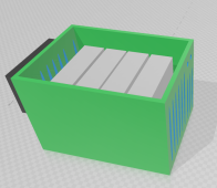
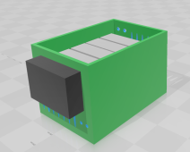
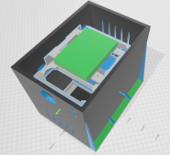
Here is the 1st design for the box the batteries & BMS will sit in. Solar charger is the black box on the side. The AC charger will mount on the back (solid side). Slots are to allow some airflow mainly for the BMS. It will end up with a cover on top as well This will make sure nothing falls or gets on top of the batteries. Walls are pretty thick at 10mm which is prob overkill. even have some slots open on the back of the solar charger for cooling (prob not even needed)

Box will be printed in ABS or possibly Nylon, heck maybe even CF if I have enough.

This will also give me something to make sure the big case I planned on using will work as I will have something to go to the store and ensure a good fit for it & everything else.
 

Attachments

  • box view 1.png
    box view 1.png
    161 KB · Views: 3
  • box view 2.png
    box view 2.png
    90.8 KB · Views: 3
I am fairly good with electrical, at least with sizing things (still struggle with schematics). There is no way I would use something like the one I am going to use for 175a like the guy in one of those reviews. Now, I can see the quality not being all that great and plastic breaking. I may end up going with a SSR which would be better in the long run and something I was already thinking about.
You lost me at "SSR".

Abbreviations get harder to decipher the older I get.
 
I'm waiting on the spec sheet from Eve for the 160ah so I can figure out what the fixture parameters are. If they are similar to the 205ah then I have spacers that I will be using & secured by tape or a retainer I will make. I am not going to be doing any threaded rod, springs, etc. Read through too many pages to go down the rabbit hole of the topic. It's like asking a car guy which brand of oil is best. If it means I get 1000 less cycles out of the bank, that's fine I can live with that as I dont need another 3+ years of charge cycles. At the most it would only be cycled once a day from 10% SOC to 100%.

Too many opinions I think on the topic of compression.
 
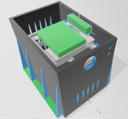
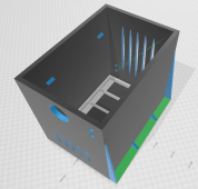
Spent the morning finishing up the box for the battery, BMS & shunt. Charge controller, 120v charger & inverter will mount to the box. If you have Windows 3D viewer (free from store) you can look at it in 3D. Going to be 3 1/2 days to print the box. Should be done by the time the batteries get here. 3D file is here: https://drive.google.com/file/d/1sV5SEB5k0hZbMsa_01ZtE5wfnUCwK3TQ/view?usp=sharing

Had to made some adjustments to the box, but not much. Overall dimensions are 302x207x250mm.

The batteries will sit in the case with separators and then a top piece will go on that will keep them in place from clips on the side of the case. On top of that is where the BMS will be mounted. There will be a temp controlled fan to blow across the BMS a well as vents on each side that will get air from a temp controlled fan as well. The fans will be controlled by an ESP8266 and a couple of Dallas DS18B20 sensors. The Arduino, relays, 12v buck converter & Raspberry zero will be mounded to the side of the case. I use the raspberry zero as a Wi-Fi access point.

The Rigid case will work perfectly. Have rubber foam on the bottom of the case. The battery case will be secured from the bottom of the Rigid case.

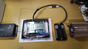
Still need to figure the best placement for the 120v input (for charging) and where to put the fuse panel. Don't like where I have these in the mock up pictures previously.

So far everything looks like it's going to work out from the mockup pictures. Only thing I am waiting on now is the batteries.

Still undecided about a disconnect switch. BMS has ability for adding one. Need to research more to understand pro/con for doing this.

Budget is still holding as well. Only thing I will need for the final assembly will be the cables for the charge controller & main +/- 4ga cables which I'll have the neighbor make for me.

Rest of the weekend is going to be spent starting to mount the power outlets, display, fans & fuse panel (once I figure out where I want to put it). Have multiple printers going making brackets as well as the box.
 

Attachments

  • box v2 bms and shunt.png
    box v2 bms and shunt.png
    304.4 KB · Views: 4
  • box v2 empty.png
    box v2 empty.png
    254.4 KB · Views: 4
  • box v2.png
    box v2.png
    260.2 KB · Views: 4
  • wiring mock up.jpg
    wiring mock up.jpg
    85.3 KB · Views: 4
Yup, waiting to see which ones come with them. Backup is to go with flex bus bars. Extra expense, but wont hurt by going that route.
 
Yup, waiting to see which ones come with them. Backup is to go with flex bus bars. Extra expense, but wont hurt by going that route.
I could be mistaken but I'm thinking someone was saying, a couple weeks ago, they got some flex busbars that turned out to be Brass.
 
Backup to the backup for the bus bars is to just make some with lugs & 2ga.

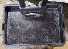
Have a lid/shelf now for the box. Gives a few inches at the top where I can put misc things like charging cord, solar panel cables, etc. The front of the Rigid toolbox has a lip for it to sit on but the back does so I will need to epoxy some brackets for the back to rest on.
 
Shelf is 1/4" osb with a fiberglass layer on top of it. Came from a crate that was used by a video production company to haul their equipment around it. It was going to go in the trash cause it had a big hole in the side so figured I could cut up a piece to fit.

Handle I had laying around so figured I would use it.
 

Attachments

  • shelf.jpg
    shelf.jpg
    369.1 KB · Views: 3
Shelf is 1/4" osb with a fiberglass layer on top of it. Came from a crate that was used by a video production company to haul their equipment around it. It was going to go in the trash cause it had a big hole in the side so figured I could cut up a piece to fit.

Handle I had laying around so figured I would use it.
? Diving behind production companies can be big business. Been there, done that. Good job.

I like your idea of using 2 awg instead of busbars. A little flex in a mobile system sounds smarter than rigid, even in a Rigid box. ;)
 
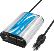
Remember now why I put this inverter in the cabinet and didn't use it much. Every time you plug it in it has a stupid alarm/siren for a couple of seconds. Goes away but wont be using it for this project. I know it's there to warn people of under/over voltage but still...on power up?

Anyway, need to see if I have any others around or I'll need to go ahead and buy one.
 
How sensitive is your equipment? It would be a shame to ruin $3000 worth of stuff with a $200 inverter.
You mentioned your neighbor making cables for you. Good reading about battery melt down in my signature.
 
Trying to find a pure sign wave inverter that is economical in the 300w-500w area isn't an easy task. I had this one sitting around, I usually put it in my wrangler when I think I may need one on an offroading trip. It is really just for charging my laptop. I have already setup the imaging computers to use 12v DC instead of their little wall chargers so that is 2 less things that need AC.
In the past, Giandel 300W Pure Sine Wave inverter worked great for me to charge laptop and other small stuff. at ~55 usd
1647140143666.png

These days, for small scale laptop charging type AC loads, Victron Phoenix Pure Sine Wave inverter is what I use and like. It has a transformer and is more bulky than the Giandel 300W. The main appeal is programmable function, data monitoring, and it can handle a surge better than giandel. I have been using the phoenix 12/500 (12V, 500VA) (~160 usd) with a 100Ah LFP battery pack and it works great and is fairly quiet when staying below the max power rating, generally 100% silent below 50W. Powering a glue gun or charging a laptop, no sweat.


targeting the 300w-500w area:

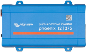
Specifically, maybe the Victron Phoenix 12/375 (12V, 375VA) might be an option at ~130 usd
1647140116800.png

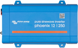
The next one down in power capacity is Victron Phoenix 12/250 (12V, 250VA) at ~100 usd
1647140375241.png

all the phoenix ones are pure sine wave as far as i gather. excited to see where this solar powered sky observation project goes! ???
 
Back
Top