diy solar

diy solar

Van Conversion Wiring Diagram, Please Review

dudedogvan

New Member
Joined
Mar 10, 2022
Messages
95
Total noob, first Solar system, first wiring diagram I've ever made for anything. Please review and help me make sure I'm not gonna burn down my van with me and my dog inside it! I haven't ordered components yet.
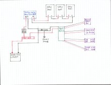
  • Outside of the fuse block for DC appliances where else do I need breakers/fuses?
  • Do I need a main fuse on the battery?
Y'all are awesome!!!Rock'n'Roll

van build wiring diagram.jpg
 
Its good to have a double pole single throw means of disconnect between the pv panels and the solar charge controller.
Suggest using a fused busbar for the positive side.
You should have a fuse on the feeder to the fuse block.
You should have a fuse as close as possible to the battery positive.
You don't need between the solar charge controller and the positive busbar, suggest a fuse instead.
You might want to put a disconnect switch after the fuse on the battery circuit.
 
  • Like
Reactions: Zil
You should install another fuse right at the + battery terminal incase you have shorted wiring.
 
No inverter?
The only thing I really need an inverter for is my laptop and I'm gonna build a little DC charger for it with a cig socket plug to a 19V 5A DC step up to my magsafe 1 connection. Otherwise I have a cheap 410 MSW inverter with a cig socket plug I can plug into the cig socket coming out of the fuse block in a pinch. Just don't wanna spend another $300-$400 bucks on something I feel like I can work around right now. I know the MSW sucks, but it'll work in a little pinch.

How bout a shunt?
Do I need a shunt? Is it for battery charge/discharge current monitoring?
Its good to have a double pole single throw means of disconnect between the pv panels and the solar charge controller.
Does this switch need to be rated for 50A or just a simple toggle/rocker switch will do?
Suggest using a fused busbar for the positive side.
How many amps does this need to be?
You should have a fuse as close as possible to the battery positive.
How many amps does this need to be?
You don't need between the solar charge controller and the positive busbar, suggest a fuse instead.
Your saying I don't need the 60A breaker. Put in a 60A fuse?
You might want to put a disconnect switch after the fuse on the battery circuit.
Is this like a master switch for the system?

Lastly, in Will's videos on 400w van systems he uses a large main fuse between the SCC, inverter and fuse box. Like right here:
website-design-solar-system.jpg


Do I need this? Also he's got that 50A breaker in there, that's why I put the 60A one in mine.

Lastly, lastly, do you want to draw a diagram with your recommendations? It'll probably be better
 
Do I need a shunt? Is it for battery charge/discharge current monitoring?
It gives you a much better indication of the state of charge of your battery than just voltage.
Does this switch need to be rated for 50A or just a simple toggle/rocker switch will do?
Depends on the voltage and amperage rating of your panels.
The wire will be awg so the switch should be rated for 30amps at the open circuit voltage of the string.
How many amps does this need to be?
Not a direct answer to your question but > 150 amps
This will work well

How many amps does this need to be?

4 awg wire with 150 amp mrbf fuse would be ideal
Your saying I don't need the 60A breaker. Put in a 60A fuse?
Yes.
An MRBF fuse to fit the fused busbar I recommended above.

Is this like a master switch for the system?
Yes.
Lastly, lastly, do you want to draw a diagram with your recommendations? It'll probably be better
Code:
legend {
    {} { functional block }
    nnn|NNN| { fused busbar position where nnn is wire size in awg and NNN is the fuse rating in amps }
    nnn|UUU| { un-fused busbar position where nnn is wire size in awg }
    <-> { bi-directional current flow }
    -> { uni-directional current flow }
    <- { uni-directional current flow }
    dpst { double pole single through switch }
    @ { back reference }
}
dc_domain {
    busbars {
        positive {
            004|UUU|<->150A_breaker<->battery
            006|100|<-scc<-dpst<-panels
            006|100|->battery_protect->fuse_block.feeders
        }
        negative {
            004|UUU|<->shunt<->battery
            006|UUU|->scc->dpst->panels
            006|UUU|<-fuse_block.feeders
            016|UUU|<->chassis_bond
        }
    }
    fuse_block {
        feeders {
            positive@
            negative@
        }
        branches {
            positive {
                010|030|->fan
                010|030|->fridge
                010|030|->combo socket
                010|030|->combo socket
                016|001|->shunt_positive
            }
            negative {
                010|UUU|<-fan
                010|UUU|<-fridge
                010|UUU|<-combo_socket
                010|UUU|<-combo_socket
                016|UUU|<-batter_protect_ground
                010|UUU|<->chassis_bond
            }
        }
    }
}
 
Last edited:
For the shunt positive you use an 1 amp automotive style fuse.
Put it on top of an MRBF fuse on the last position on the fused busbar.
Fused MRBF busbars really save space.
 
While I agree with most of @smoothJoey's recommendations, I would leave the 60A breaker for the SCC. This allows you to use it as a disconnect if you need to isolate the solar for some reason while still running your DC loads.

You might wish to add a battery protect (such as the Victron Battery Protect) between the fuse block and the bus bar. This ensures that your DC loads can't over discharge the battery and it can also act as a disconnect of your DC loads if ever needed.
 
This is a less expensive build.
The trick is double up the 10 awg wires into the solar charge controller.

Code:
legend {
    {} { functional block }
    nnn|NNN| { fused busbar position where nnn is wire size in awg and NNN is the fuse rating in amps }
    nnn|UUU| { un-fused busbar position where nnn is wire size in awg }
    <-> { bi-directional current flow }
    -> { uni-directional current flow }
    <- { uni-directional current flow }
    dpst { double pole single through switch }
    @ { back reference }
}
dc_domain {
    fuse_block {
        feeders {
            positive<->100A_breaker<->battery
            negative<->shunt<->battery
        }
        branches {
            positive {
                010|030|<-scc.out
                010|030|<-scc.out
                010|030|->fan
                010|030|->fridge
                010|030|->combo socket
                010|030|->combo socket
                016|001|->shunt_positive
            }
            negative {
                010|UUU|->scc.out
                010|UUU|->scc.out
                010|UUU|<-fan
                010|UUU|<-fridge
                010|UUU|<-combo_socket
                010|UUU|<-combo_socket
                010|UUU|<->chassis_bond
            }
        }
        scc {
            in {
                positive<-dpst<-panels(10 awg)
                negative->dpst->panels(10 awg)
            }
            out {
                positive@
                negative@
            }
        }
    }
}
 
Last edited:
While I agree with most of @smoothJoey's recommendations, I would leave the 60A breaker for the SCC. This allows you to use it as a disconnect if you need to isolate the solar for some reason while still running your DC loads.
The double pole single throw switch isolates the charge source.
Why would you need to isolate the system side of the scc?
You might wish to add a battery protect (such as the Victron Battery Protect) between the fuse block and the bus bar. This ensures that your DC loads can't over discharge the battery and it can also act as a disconnect of your DC loads if ever needed.
Agree.
 
Why would you need to isolate the system side of the scc?
Possibly for maintenance or perhaps the SCC is acting up and you need to disconnect it for repair/replacement. Granted this won't be used much. So far I've only used my SCC breaker two or three times and they were all during the initial setup of my trailer's electrical system.
 
Possibly for maintenance or perhaps the SCC is acting up and you need to disconnect it for repair/replacement. Granted this won't be used much. So far I've only used my SCC breaker two or three times and they were all during the initial setup of my trailer's electrical system.
The master switch covers that.
Or in the new drawing just remove the blade fuses for the scc circuit.
Of course you will isolate the pv side first though.
 
But that kills all of the DC loads too.
For a small system like this I don't think it matters much.
I still don't see a compelling use case for a breaker on the system side of the solar charge controller.
On top of that he can just remove the blade fuses to isolate the system side of the solar charge controller.
 
Code:
Code:
legend {
    {} { functional block }
    nnn|NNN| { fused busbar position where nnn is wire size in awg and NNN is the fuse rating in amps }
    nnn|UUU| { un-fused busbar position where nnn is wire size in awg }
    <-> { bi-directional current flow }
    -> { uni-directional current flow }
    <- { uni-directional current flow }
    dpst { double pole single through switch }
}
dc_domain {
    busbars {
        positive {
            004|UUU|<->150A_mrbf_fuse<->disconnect_switch<->battery
            006|100|<-scc<-dpst<-panels
            006|100|->fuse_block
            016|001|->shunt_positive
        }
        negative {
            004|UUU|<->shunt<->battery
            006|UUU|->scc->dpst->panels
            006|UUU|<-fuse_block
            016|UUU|<->chassis_bond
        }
    }
}
Joey I don't know what any of this code means man, haha
 
Joey I don't know what any of this code means man, haha
Its not code it just shows what connects to what.
A system is basically a ladder where the busbars are the risers and the circuits are the rungs.
 
Its not code it just shows what connects to what.
A system is basically a ladder where the busbars are the risers and the circuits are the rungs.
Ok now that I try to actually understand it I see I may be able to make sense of it. How do you already know wires sizes without knowing run distances?
 
Ok now that I try to actually understand it I see I may be able to make sense of it. How do you already know wires sizes without knowing run distances?
The core of the system should all be close enough together that voltage drop is not an issue.
I oversized the branch circuits to the maximum size and fused for the wire.
EZPZ.
If you want we can tweak the branch circuits.
Or I can teach you how to size your own.
 
Back
Top