FilterGuy
Solar Engineering Consultant - EG4 and Consumers
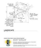
1. I plan on grounding the solar panel frames and mounts. While this would violate #14 in the manual as stated above, this will be required by code so #11 (following code) would trump that. As I plan on using Iron Ridge roof mounting, that will be done using what you refer to as the traditional method.
2. I will use the breaker in grounding method you describe.
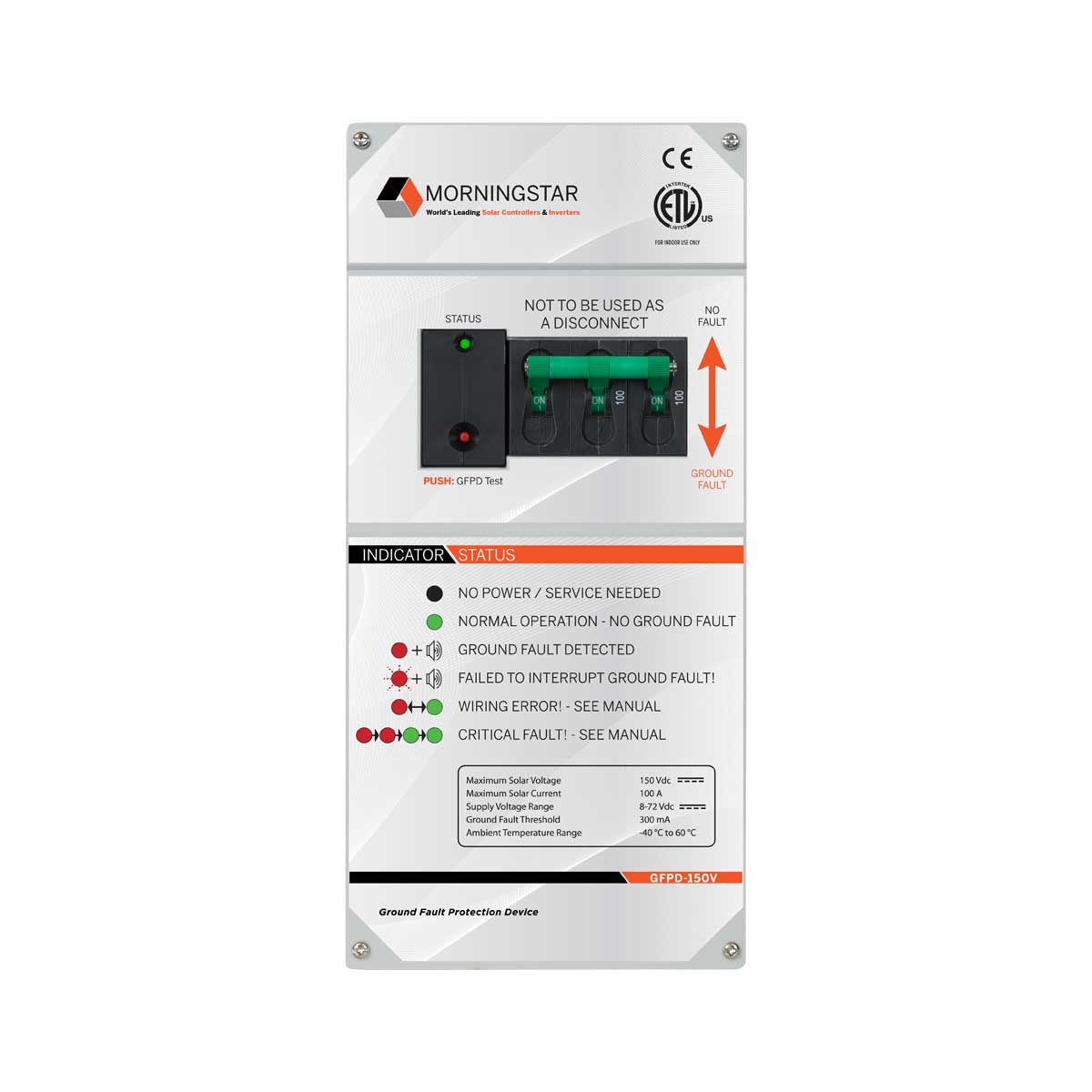
This is where things get wonky. I don't think the manual is trying to say not to ground the frames. I *think* it is saying don't ground the actual PV circuit. However, if you use the .5A breaker as the ground fault detection, it effectively grounds the PV circuit. Consequently, I don't know how anyone has added ground fault protection to the MPP inverters. (I have never done it.... but I never had to pass inspection)
I would advise asking MPP or Ian how it should be done.
Correct, They are ganged breakers. The theory is that there should never be current going to ground so if there is 1/5 of an amp, something is wrong and the 1/5A breaker trips...... tripping all the other breakers.3. I am confused by the diagram on page 3 of your linked document (it's not you, it's me). I'm thinking that you have a ganged breaker, one that is low current for the equipment ground (0.5A) with one that is high current (for the positive wires from the solar arrays). If I'm not mistaken, a trip in one will trip the other. It appears to me that the equipment ground from the solar panels is tied to the current carrying conductor (which will be the negative wire from the solar panels) in the low current breaker. I'm having a hard time understanding where the equipment ground from the solar panels ties into the equipment ground from the main. One thing is obvious is that it should NOT have it's own grounding electrode.


")
.jpg")