Batteries cells naturally compress and expand into environment and state of charge. According to the manufacturers life is extended if they are compressed at approximately seven psi and never exceed approximately 17 psi.So are you guys talking about giving way to the batteries to expand ? I thought that we compress them so they won't expand, to prolong life..
You are using an out of date browser. It may not display this or other websites correctly.
You should upgrade or use an alternative browser.
You should upgrade or use an alternative browser.
Another Cell Compression Thread, this time about foam
- Thread starter Zwy
- Start date
Please read my other replies in this post for a better understanding of the type of material that I have decided to use through extensive researchI bought my batteries before I found this forum based solely on the capacity I needed to run my fridge and the fact they were in the US. If I had found the forum first I would probably still be trying to decide what to get.I'd probably also still be waiting on cells to ship from china.
My cells came with a couple of long zip ties and a small roll of double sided squishy tape to stick between them. I thought the foam was an odd choice until I saw the cells beginning to swell and the pack got over 1/4" wider the first time I charged them up. I want to add capacity down the road so may have to reconfigure and I didn't want to damage the cells trying to pull them apart, so I instead slipped some 1mm thick foam sheets between my cells. I cut the foam from some packing envelopes that got away from someone and floated into my yard after a thunderstorm. I cut them a little bit long and used slits in the tops to keep the bms wires organized. After seeing a couple of drop-in LiFePo4 battery teardown and reading a couple of posts here on the forum I modified my cell holder to fit snug around the cells and constrain them, and I haven't noticed the pack moving any more. These are 200ah cells. I imagine the larger cells expand more.
Also, before I found the foam envelopes in the yard, I was going to experiment with paperboard or cardboard or construction paper between the cells to allow them to move a little bit. I was also considering something like felt or fiberglass matt, anything to let them flex a little bit but remain constrained.
View attachment 35175
Tape will hold them together quite well however they do not allow for proper compression if your goal is to achieve longevityI just used polyimide on the cells then 3M VHB tape on top of the polyimide tape (only so that I can remove both of them more easily; VHB is hard to get off once it has set). I haven't implemented my cell-compression fixture yet but they are sitting there stuck together quite nicely, and I picked up 4 cells to lift them into my battery box and they stayed together with no slippage.
Looking at ways of compression for the battery pack that i am building. Anybody using EVA foam ? It is easy to get hold off and cheap. The stiffer types like EVA75 seem to be a relatively good fit, even if the compression set is a bit high from some manufacturers.
I guess the main problem is the lack of reliable datasheet on the EVA foam from hobby stores.
It seems to be impossible to get Poron or similar foams in Europe, especially in Scandinavia.
I guess the main problem is the lack of reliable datasheet on the EVA foam from hobby stores.
It seems to be impossible to get Poron or similar foams in Europe, especially in Scandinavia.
You might want to get a small piece and test it for memory (taking a set when under pressure). I tested a sheet of closed cell ethafoam by resting a lead-acid battery on it for a few weeks. It took a set pretty well, but it eventually came back to the original shape. The point is that you want a foam that continues to apply the same force under compression, even after long-term use.Looking at ways of compression for the battery pack that i am building. Anybody using EVA foam ? It is easy to get hold off and cheap. The stiffer types like EVA75 seem to be a relatively good fit, even if the compression set is a bit high from some manufacturers.
I guess the main problem is the lack of reliable datasheet on the EVA foam from hobby stores.
It seems to be impossible to get Poron or similar foams in Europe, especially in Scandinavia.
It seems to me that Poron may be a special blend of neoprene foam, similar to wetsuit material (but without the cloth layer). If I can get the time to set up my strain gauge, I plan to do a long-term test of various foam materials.
curiouscarbon
Science Penguin
- Joined
- Jun 29, 2020
- Messages
- 3,028
cool!You might want to get a small piece and test it for memory (taking a set when under pressure). I tested a sheet of closed cell ethafoam by resting a lead-acid battery on it for a few weeks. It took a set pretty well, but it eventually came back to the original shape. The point is that you want a foam that continues to apply the same force under compression, even after long-term use.
It seems to me that Poron may be a special blend of neoprene foam, similar to wetsuit material (but without the cloth layer). If I can get the time to set up my strain gauge, I plan to do a long-term test of various foam materials.
the EV specific poron, couldn't source
got some light blue poron rolls on amazon
"poron 4000 royal blue"
it's the type for padding prosthetics and stuff though, i think. still should be fun to rest a cell on it for a while and observe any deformations
Zwy
Emperor Of Solar
Poron is open cell. This allows elasticity over time where as closed cell will lose the air in between cells over time.You might want to get a small piece and test it for memory (taking a set when under pressure). I tested a sheet of closed cell ethafoam by resting a lead-acid battery on it for a few weeks. It took a set pretty well, but it eventually came back to the original shape. The point is that you want a foam that continues to apply the same force under compression, even after long-term use.
It seems to me that Poron may be a special blend of neoprene foam, similar to wetsuit material (but without the cloth layer). If I can get the time to set up my strain gauge, I plan to do a long-term test of various foam materials.
I've read hundreds of posts about compression and all the clever ways of interpreting/achieving the force that the cell manufacture's data sheet calls out, so I'm wondering why two of the largest battery manufacturers, CATL and EVE just take a very simple approach: They just line up the cells, apply X-amount of force and then quickly laser weld an aluminum sheet metal surround and call it good? No springs, no foam, no insulation between cells. One would think that if they're mass producing battery packs made of prismatic cells they would be very concerned about getting it right or face a ton of product returns or potential damage liability.
You can see in the following two videos that they do compress the cells before welding up the case, but there's no evidence of any method or mechanism that would allow the cell to "breathe" once it's fixture was set.
These are the guys that are writing the data sheets that we're trying to interpret, wouldn't this be a physical example of what they're trying to say?
EVE Pack Assembly. Note the compression mechanism at the 30-second mark of the timeline.
CATL LFP Battery Production. Cell compression starts at about the 1:58 point in the timeline.
curiouscarbon
Science Penguin
- Joined
- Jun 29, 2020
- Messages
- 3,028
The extra length of springs is unappealing to me.
By using threaded rod and load cells, I intend to monitor the pressure and loosen if it goes too high.
Ideally, I wish for no/minimal deformation of the case while also staying below the max pressure figure in datasheet.
Thank you for the post and videos!
Interesting that they pre-apply the force and then laser weld in place. quite clever in my opinion for quick/efficient manufacture ability.
curiouscarbon
Science Penguin
- Joined
- Jun 29, 2020
- Messages
- 3,028
good point. if the fixture is solid, the need for extra insulation to mitigate vibration induced chafing should be reduced.I've read hundreds of posts about compression and all the clever ways of interpreting/achieving the force that the cell manufacture's data sheet calls out, so I'm wondering why two of the largest battery manufacturers, CATL and EVE just take a very simple approach: They just line up the cells, apply X-amount of force and then quickly laser weld an aluminum sheet metal surround and call it good? No springs, no foam, no insulation between cells. One would think that if they're mass producing battery packs made of prismatic cells they would be very concerned about getting it right or face a ton of product returns or potential damage liability.
You can see in the following two videos that they do compress the cells before welding up the case, but there's no evidence of any method or mechanism that would allow the cell to "breathe" once it's fixture was set.
These are the guys that are writing the data sheets that we're trying to interpret, wouldn't this be a physical example of what they're trying to say?
EVE Pack Assembly. Note the compression mechanism at the 30-second mark of the timeline.
CATL LFP Battery Production. Cell compression starts at about the 1:58 point in the timeline.
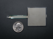
would be cool to include some sort of force sensitive resistor on each end of the pack to detect serious overpressure failure mode.
cheap material wise.
careful observation of reports indicates that expansion/contraction of the cell is confined mostly to the center of the face, so the sensor does not need to be the full size of the cell, in my opinion
e.g.
TorC
Solar Enthusiast
- Joined
- Jan 13, 2022
- Messages
- 514
Interesting find, @Dan1376. On reading that I start to wonder what the reason for the cell compression cycle life graph really is. I'm currently wondering if it could it be that the force per area measurement means nothing, and it's really a question of limiting expansion, with the force having as much to do with the case corners and how they deform to provide optimum pressure internally.
Even the test setup design that produced that graph: have we been misinterpreting them all along, and the design really is, "At X SOC assemble a fixed case with P pressure at time of assembly."
Even the test setup design that produced that graph: have we been misinterpreting them all along, and the design really is, "At X SOC assemble a fixed case with P pressure at time of assembly."
One important thing to remember is that when they design a mechanical enclosure they can design it with enough compliance to account for cell expansion and contraction.
Thin steel/aluminum plates are springy. There is no problem to make a metal case without springs if the case itself will act as the spring. I am 100 % sure that these thin plates that is being welded shut will deflect 1-3 mm under 300 kgf. For smaller packs that is sufficient.
For us that does this diy, it is a bit more difficult since most of us does not run simulations on optimal case thickness to ensure that the case is sufficiently compliant.
matt2006
DIY Solar since 2016
I was told by a guy that builds Ford Rangers into EV's that EVA foam is the best for between lifepo4 cells.
Zwy
Emperor Of Solar
EVA foam is closed cell. Over time, it will compress without returning to original thickness as the air/gas in the voids eventually will leak out under long term compression. Second concern is flammability, I didn't look to see what standards it meets but one should research it before using EVA foam.I was told by a guy that builds Ford Rangers into EV's that EVA foam is the best for between lifepo4 cells.
curiouscarbon
Science Penguin
- Joined
- Jun 29, 2020
- Messages
- 3,028
poron foam uses the mechanics of the material to push back, from what i gather, (less degrade over time?)
some foam use force of air bubble to provide push, but it leaks out of small internal holes/pores. (more degrade over time with air leak.)
(degrade = force reduces over time with continued pressure)
i'm still learning
thank you everyone for info!
some foam use force of air bubble to provide push, but it leaks out of small internal holes/pores. (more degrade over time with air leak.)
(degrade = force reduces over time with continued pressure)
i'm still learning
thank you everyone for info!
OK, so I bought the Poron 50-15250 sheet from McMaster.
I used the chart provided by the manufacturer to estimate the compression for my 4S battery. I have cut most of the parts for the frame but have not put it together yet because I have not drilled all the screw holes. This battery will have one sheet of foam compressed roughly 15%, which should yield about 9 PSI. One 1/4" sheet should also allow for 0.5mm (~0.020") expansion of each cell, for a total of 0.080" expansion and a pressure just under the magic 18 PSI maximum specified by EVE. Here is the manufacturer's chart: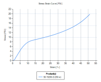
This should work well, depending on the long-term performance of the foam, but the more pressing question is what will I do for the two 16S batteries I am also making? One sheet of foam is not enough to allow for that much expansion, but two sheets will cover eight cells, and I can build boxes of eight and get my two 16S batteries that way. The question now is, what happens when I use two sheets of foam in one stack?
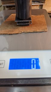
Rather than blindly trust the chart above and make a curve assuming they will behave as parallel springs, I decided to measure the stuff. It isn't a true linear spring after all, and I figured out how to do it with a few things I have lying around (such as a kitchen scale and a CNC mill). Here we go!
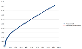
First, I had to measure the force shown on the scale at different displacements since the pan moves down slightly as you press on it. I put the scale on the mill bed, added a small (about 4" square) piece of 1/8" masonite to distribute the force on the pan, and proceeded to press down on the scale with a 1.25" diameter cylinder. I recorded the scale readings every 0.001" from 0" to 0.046", where the scale was near its upper limit.
I then made a spreadsheet with the recorded values and fit a seventh-order polynomial to the data, which gives me a displacement adjustment per force measured so I can calculate the actual amount the foam displaced under that load. Here is the adjustment curve (X is grams, Y is inches):
I cut two pieces of foam. The goal was exactly one square inch each, but the foam is just a bit pesky to cut, so I wound up with one at 1.035 and the other 1.045 square inches. The final adjusted force measurements are normalized by these values to give pounds per square inch. I measured the first square of foam by placing it on the scale and topping it with a 1.25" square piece of 1/16" plastic to distribute the force on the foam. After zeroing the scale, I proceeded to press the foam in 0.010" increments from 0" to 0.200", where the scale was close enough to its maximum value (and the foam was compressed 80%). I then replaced the foam with piece number two and repeated the experiment.
Finally, I made a Poron sandwich with foam, plastic, foam, and plastic on the scale and pressed that stack from 0" to 0.360", where the scale was near its maximum. All of this measuring was very slow going since I had to wait about a minute at each step to let the foam stabilize. It was easy to see that it was losing quite a bit of the initial force after changing the displacement, so I had to let it settle a bit. I could not wait for it to stop completely because the scale would go to sleep. It was also 97°F (35°C) in my shop today with the doors open, so I was OK with watching the force slow down and making an estimate after one minute. I then made a spreadsheet with the data.
I used the scale adjustment curve to subtract the scale displacement from my recorded displacement values so that I now have foam displacement only. I used the area adjustments for both pieces to normalize the force measurements to PSI. But enough of all that, here's the result:
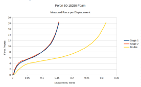
So, it seems that a stack of eight cells with two sheets of foam can expand up to 8X0.5mm = 4mm (~0.160") and still be below 18 PSI if I start with a 0.2" total (0.1" per sheet) displacement in the foam. That should give me a range of about 7.5 to 18 PSI over the expected expansion of the cells. It also seems that my 4S battery will start at about 5 PSI, not 9 PSI. Oh, well.
Enjoy!
I used the chart provided by the manufacturer to estimate the compression for my 4S battery. I have cut most of the parts for the frame but have not put it together yet because I have not drilled all the screw holes. This battery will have one sheet of foam compressed roughly 15%, which should yield about 9 PSI. One 1/4" sheet should also allow for 0.5mm (~0.020") expansion of each cell, for a total of 0.080" expansion and a pressure just under the magic 18 PSI maximum specified by EVE. Here is the manufacturer's chart:

This should work well, depending on the long-term performance of the foam, but the more pressing question is what will I do for the two 16S batteries I am also making? One sheet of foam is not enough to allow for that much expansion, but two sheets will cover eight cells, and I can build boxes of eight and get my two 16S batteries that way. The question now is, what happens when I use two sheets of foam in one stack?
Rather than blindly trust the chart above and make a curve assuming they will behave as parallel springs, I decided to measure the stuff. It isn't a true linear spring after all, and I figured out how to do it with a few things I have lying around (such as a kitchen scale and a CNC mill). Here we go!
First, I had to measure the force shown on the scale at different displacements since the pan moves down slightly as you press on it. I put the scale on the mill bed, added a small (about 4" square) piece of 1/8" masonite to distribute the force on the pan, and proceeded to press down on the scale with a 1.25" diameter cylinder. I recorded the scale readings every 0.001" from 0" to 0.046", where the scale was near its upper limit.
I then made a spreadsheet with the recorded values and fit a seventh-order polynomial to the data, which gives me a displacement adjustment per force measured so I can calculate the actual amount the foam displaced under that load. Here is the adjustment curve (X is grams, Y is inches):

I cut two pieces of foam. The goal was exactly one square inch each, but the foam is just a bit pesky to cut, so I wound up with one at 1.035 and the other 1.045 square inches. The final adjusted force measurements are normalized by these values to give pounds per square inch. I measured the first square of foam by placing it on the scale and topping it with a 1.25" square piece of 1/16" plastic to distribute the force on the foam. After zeroing the scale, I proceeded to press the foam in 0.010" increments from 0" to 0.200", where the scale was close enough to its maximum value (and the foam was compressed 80%). I then replaced the foam with piece number two and repeated the experiment.
Finally, I made a Poron sandwich with foam, plastic, foam, and plastic on the scale and pressed that stack from 0" to 0.360", where the scale was near its maximum. All of this measuring was very slow going since I had to wait about a minute at each step to let the foam stabilize. It was easy to see that it was losing quite a bit of the initial force after changing the displacement, so I had to let it settle a bit. I could not wait for it to stop completely because the scale would go to sleep. It was also 97°F (35°C) in my shop today with the doors open, so I was OK with watching the force slow down and making an estimate after one minute. I then made a spreadsheet with the data.
I used the scale adjustment curve to subtract the scale displacement from my recorded displacement values so that I now have foam displacement only. I used the area adjustments for both pieces to normalize the force measurements to PSI. But enough of all that, here's the result:

So, it seems that a stack of eight cells with two sheets of foam can expand up to 8X0.5mm = 4mm (~0.160") and still be below 18 PSI if I start with a 0.2" total (0.1" per sheet) displacement in the foam. That should give me a range of about 7.5 to 18 PSI over the expected expansion of the cells. It also seems that my 4S battery will start at about 5 PSI, not 9 PSI. Oh, well.
Enjoy!
curiouscarbon
Science Penguin
- Joined
- Jun 29, 2020
- Messages
- 3,028
Zwy
Emperor Of Solar
You intend to only use 2 sheets total? One on each end of the pack? This was 1/4" Poron correct? In the chart above, 0.250" compression? Or should it be 0.025"? If it is 0.250", that would be the total thickness of 1/4" Poron. Basically what the chart is currently showing is for 2 sheets of 1/4" Poron, you compress 25% for around 5 psi and 50% yields around 9 psi.View attachment 99140
So, it seems that a stack of eight cells with two sheets of foam can expand up to 8X0.5mm = 4mm (~0.160") and still be below 18 PSI if I start with a 0.2" total (0.1" per sheet) displacement in the foam. That should give me a range of about 7.5 to 18 PSI over the expected expansion of the cells. It also seems that my 4S battery will start at about 5 PSI, not 9 PSI. Oh, well.
Enjoy!
I build my packs with foam between each cell and on the ends. I'll have to look at my figures for a 16S pack in a straight line what I compress at. That would take 17 sheets (however it was 1/8" or 3/16") and I don't think it would have been close to 1" of compression. I do use a fully charged pack length for compression computation.
Yes, two sheets for eight cells. I will probably put one on each end, but I don't think it matters much. I have other reasons for grouping my cells by eight instead of sixteen, and one major reason is that I can lift eight. If I need to break a pack I can remove the wires and lift the one I want.You intend to only use 2 sheets total? One on each end of the pack? This was 1/4" Poron correct? In the chart above, 0.250" compression? Or should it be 0.025"? If it is 0.250", that would be the total thickness of 1/4" Poron. Basically what the chart is currently showing is for 2 sheets of 1/4" Poron, you compress 25% for around 5 psi and 50% yields around 9 psi.
I build my packs with foam between each cell and on the ends. I'll have to look at my figures for a 16S pack in a straight line what I compress at. That would take 17 sheets (however it was 1/8" or 3/16") and I don't think it would have been close to 1" of compression. I do use a fully charged pack length for compression computation.
0.250" compression is correct. The "Double" curve is two sheets stacked, which is 0.5" thick.
Similar threads
- Replies
- 112
- Views
- 9K


