You are using an out of date browser. It may not display this or other websites correctly.
You should upgrade or use an alternative browser.
You should upgrade or use an alternative browser.
Another Cell Compression Thread, this time about foam
- Thread starter Zwy
- Start date
OK, so I bought the Poron 50-15250 sheet from McMaster.
I used the chart provided by the manufacturer to estimate the compression for my 4S battery. I have cut most of the parts for the frame but have not put it together yet because I have not drilled all the screw holes. This battery will have one sheet of foam compressed roughly 15%, which should yield about 9 PSI. One 1/4" sheet should also allow for 0.5mm (~0.020") expansion of each cell, for a total of 0.080" expansion and a pressure just under the magic 18 PSI maximum specified by EVE. Here is the manufacturer's chart: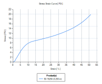
This should work well, depending on the long-term performance of the foam, but the more pressing question is what will I do for the two 16S batteries I am also making? One sheet of foam is not enough to allow for that much expansion, but two sheets will cover eight cells, and I can build boxes of eight and get my two 16S batteries that way. The question now is, what happens when I use two sheets of foam in one stack?
Rather than blindly trust the chart above and make a curve assuming they will behave as parallel springs, I decided to measure the stuff. It isn't a true linear spring after all, and I figured out how to do it with a few things I have lying around (such as a kitchen scale and a CNC mill). Here we go!
First, I had to measure the force shown on the scale at different displacements since the pan moves down slightly as you press on it. I put the scale on the mill bed, added a small (about 4" square) piece of 1/8" masonite to distribute the force on the pan, and proceeded to press down on the scale with a 1.25" diameter cylinder. I recorded the scale readings every 0.001" from 0" to 0.046", where the scale was near its upper limit.
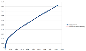
I then made a spreadsheet with the recorded values and fit a seventh-order polynomial to the data, which gives me a displacement adjustment per force measured so I can calculate the actual amount the foam displaced under that load. Here is the adjustment curve (X is grams, Y is inches):
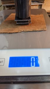
I cut two pieces of foam. The goal was exactly one square inch each, but the foam is just a bit pesky to cut, so I wound up with one at 1.035 and the other 1.045 square inches. The final adjusted force measurements are normalized by these values to give pounds per square inch. I measured the first square of foam by placing it on the scale and topping it with a 1.25" square piece of 1/16" plastic to distribute the force on the foam. After zeroing the scale, I proceeded to press the foam in 0.010" increments from 0" to 0.200", where the scale was close enough to its maximum value (and the foam was compressed 80%). I then replaced the foam with piece number two and repeated the experiment.
Finally, I made a Poron sandwich with foam, plastic, foam, and plastic on the scale and pressed that stack from 0" to 0.360", where the scale was near its maximum. All of this measuring was very slow going since I had to wait about a minute at each step to let the foam stabilize. It was easy to see that it was losing quite a bit of the initial force after changing the displacement, so I had to let it settle a bit. I could not wait for it to stop completely because the scale would go to sleep. It was also 97°F (35°C) in my shop today with the doors open, so I was OK with watching the force slow down and making an estimate after one minute. I then made a spreadsheet with the data.
I used the scale adjustment curve to subtract the scale displacement from my recorded displacement values so that I now have foam displacement only. I used the area adjustments for both pieces to normalize the force measurements to PSI. But enough of all that, here's the result:
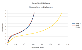
So, it seems that a stack of eight cells with two sheets of foam can expand up to 8X0.5mm = 4mm (~0.160") and still be below 18 PSI if I start with a 0.2" total (0.1" per sheet) displacement in the foam. That should give me a range of about 7.5 to 18 PSI over the expected expansion of the cells. It also seems that my 4S battery will start at about 5 PSI, not 9 PSI. Oh, well.
Enjoy!
I used the chart provided by the manufacturer to estimate the compression for my 4S battery. I have cut most of the parts for the frame but have not put it together yet because I have not drilled all the screw holes. This battery will have one sheet of foam compressed roughly 15%, which should yield about 9 PSI. One 1/4" sheet should also allow for 0.5mm (~0.020") expansion of each cell, for a total of 0.080" expansion and a pressure just under the magic 18 PSI maximum specified by EVE. Here is the manufacturer's chart:

This should work well, depending on the long-term performance of the foam, but the more pressing question is what will I do for the two 16S batteries I am also making? One sheet of foam is not enough to allow for that much expansion, but two sheets will cover eight cells, and I can build boxes of eight and get my two 16S batteries that way. The question now is, what happens when I use two sheets of foam in one stack?
Rather than blindly trust the chart above and make a curve assuming they will behave as parallel springs, I decided to measure the stuff. It isn't a true linear spring after all, and I figured out how to do it with a few things I have lying around (such as a kitchen scale and a CNC mill). Here we go!
First, I had to measure the force shown on the scale at different displacements since the pan moves down slightly as you press on it. I put the scale on the mill bed, added a small (about 4" square) piece of 1/8" masonite to distribute the force on the pan, and proceeded to press down on the scale with a 1.25" diameter cylinder. I recorded the scale readings every 0.001" from 0" to 0.046", where the scale was near its upper limit.
I then made a spreadsheet with the recorded values and fit a seventh-order polynomial to the data, which gives me a displacement adjustment per force measured so I can calculate the actual amount the foam displaced under that load. Here is the adjustment curve (X is grams, Y is inches):

I cut two pieces of foam. The goal was exactly one square inch each, but the foam is just a bit pesky to cut, so I wound up with one at 1.035 and the other 1.045 square inches. The final adjusted force measurements are normalized by these values to give pounds per square inch. I measured the first square of foam by placing it on the scale and topping it with a 1.25" square piece of 1/16" plastic to distribute the force on the foam. After zeroing the scale, I proceeded to press the foam in 0.010" increments from 0" to 0.200", where the scale was close enough to its maximum value (and the foam was compressed 80%). I then replaced the foam with piece number two and repeated the experiment.
Finally, I made a Poron sandwich with foam, plastic, foam, and plastic on the scale and pressed that stack from 0" to 0.360", where the scale was near its maximum. All of this measuring was very slow going since I had to wait about a minute at each step to let the foam stabilize. It was easy to see that it was losing quite a bit of the initial force after changing the displacement, so I had to let it settle a bit. I could not wait for it to stop completely because the scale would go to sleep. It was also 97°F (35°C) in my shop today with the doors open, so I was OK with watching the force slow down and making an estimate after one minute. I then made a spreadsheet with the data.
I used the scale adjustment curve to subtract the scale displacement from my recorded displacement values so that I now have foam displacement only. I used the area adjustments for both pieces to normalize the force measurements to PSI. But enough of all that, here's the result:

So, it seems that a stack of eight cells with two sheets of foam can expand up to 8X0.5mm = 4mm (~0.160") and still be below 18 PSI if I start with a 0.2" total (0.1" per sheet) displacement in the foam. That should give me a range of about 7.5 to 18 PSI over the expected expansion of the cells. It also seems that my 4S battery will start at about 5 PSI, not 9 PSI. Oh, well.
Enjoy!
curiouscarbon
Science Penguin
- Joined
- Jun 29, 2020
- Messages
- 3,017
Zwy
Emperor Of Solar
You intend to only use 2 sheets total? One on each end of the pack? This was 1/4" Poron correct? In the chart above, 0.250" compression? Or should it be 0.025"? If it is 0.250", that would be the total thickness of 1/4" Poron. Basically what the chart is currently showing is for 2 sheets of 1/4" Poron, you compress 25% for around 5 psi and 50% yields around 9 psi.View attachment 99140
So, it seems that a stack of eight cells with two sheets of foam can expand up to 8X0.5mm = 4mm (~0.160") and still be below 18 PSI if I start with a 0.2" total (0.1" per sheet) displacement in the foam. That should give me a range of about 7.5 to 18 PSI over the expected expansion of the cells. It also seems that my 4S battery will start at about 5 PSI, not 9 PSI. Oh, well.
Enjoy!
I build my packs with foam between each cell and on the ends. I'll have to look at my figures for a 16S pack in a straight line what I compress at. That would take 17 sheets (however it was 1/8" or 3/16") and I don't think it would have been close to 1" of compression. I do use a fully charged pack length for compression computation.
Yes, two sheets for eight cells. I will probably put one on each end, but I don't think it matters much. I have other reasons for grouping my cells by eight instead of sixteen, and one major reason is that I can lift eight. If I need to break a pack I can remove the wires and lift the one I want.You intend to only use 2 sheets total? One on each end of the pack? This was 1/4" Poron correct? In the chart above, 0.250" compression? Or should it be 0.025"? If it is 0.250", that would be the total thickness of 1/4" Poron. Basically what the chart is currently showing is for 2 sheets of 1/4" Poron, you compress 25% for around 5 psi and 50% yields around 9 psi.
I build my packs with foam between each cell and on the ends. I'll have to look at my figures for a 16S pack in a straight line what I compress at. That would take 17 sheets (however it was 1/8" or 3/16") and I don't think it would have been close to 1" of compression. I do use a fully charged pack length for compression computation.
0.250" compression is correct. The "Double" curve is two sheets stacked, which is 0.5" thick.
Hedges
I See Electromagnetic Fields!
- Joined
- Mar 28, 2020
- Messages
- 21,532
Yes, two sheets for eight cells. I will probably put one on each end, but I don't think it matters much.
Busbars and distance between terminals?
If the goal is to let each cell expand and contract, ideally they do that without moving terminals relative to each other. For that I would think rubber sheets between all cells, and 1/2 thickness at each end.
Unless your busbars are flexible.
Flexible busbars and hard separator sheets from Docan.Busbars and distance between terminals?
If the goal is to let each cell expand and contract, ideally they do that without moving terminals relative to each other. For that I would think rubber sheets between all cells, and 1/2 thickness at each end.
Unless your busbars are flexible.
The goal is to allow expansion while maintaining the specified compression of 8 to 18 PSI. Falling short on the low end is apparently far better than exceeding the high end, so this should work out well.
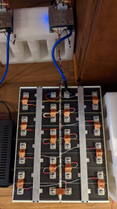
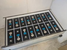
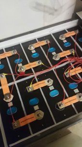
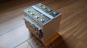
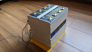
OK, so I got the first compression frame completed. This is the 4S 230Ah pack with one 1/4" sheet of Poron 50-15250 foam as a compressing agent. You can see the separator sheets from Docan sticking up between the cells. The sides and bottoms of the cells have extra material to keep from somehow shorting the cells.
The end caps are 1/4" aluminum and the straps are 1/8" aluminum, all held together with 4-40 flat head screws. My bar clamps were barely strong enough to compress the foam to line up the screw holes. Before you ask, yes, 18 screws on each end will easily hold the ~660 pound maximum force.
The JBD 200A BMS fits nicely on the side. Time to begin a top balance on these four cells!


Seplos Chris Ren
New Member
- Joined
- Jul 25, 2021
- Messages
- 38
Is the foam mentioned in the SEPLOS battery? 2mm in depth.
What is the force profile of the stack of foam used in the Seplos battery?Is the foam mentioned in the SEPLOS battery? 2mm in depth.
Zwy
Emperor Of Solar
Might need to put 4701 as a prefix
Thanks @Zwy.
Might need to put 4701 as a prefix
Regarding search, I meant specifically in McMaster. 642 Products. lol
Yes I've been looking outside of McMaster. I did see the 4701 prefix.
I'll find something. No Big Deal.
My PO shows 86375K234 as the SKU I bought.@justgary "OK, so I bought the Poron 50-15250 sheet from McMaster."
Do you happen to still have a link or the McMaster part number or sku for what you bought?
I went there and searched around but could not narrow it down enough to find anything "50-15250"?
Thank you sir!
Geo
Thank you sir!My PO shows 86375K234 as the SKU I bought.
That is a thing of beauty!
Well done sir.
Thanks. I might be inclined to just use a rigid frame if I did it again. Getting the force correct in a rigid frame seems awfully pesky though, and it was relatively easy for me to calculate the distance required to get the force with the foam.That is a thing of beauty!
Well done sir.
Photos of the 16S batteries are floating around here somewhere. I still don't have them in their final resting place due to delays on crimping the cables needed to hook everything up (as 16S2P). Soon....
Capt Bill
Sailing Options
Very Good Looking Set Up for LiFePO4s. I might have consider that if I had access to reasonably priced flex bars when I did mine. I personally think this compression is more important in EV applications, and have been concerned about internal LiFePO4 terminal damage when done with solid bus bars (as battery sides change dimensions with SOC with various Amps in and out). ... I used this other way wo compression, ... using 90 cm Bus Bars (Width: 20mm, Thickness: 2.0mm, 2-Hole distance: 72mm, Length: 90mm) ... my 3 x 24v 280Ah EVE LiFePO4s Battery Banks are currently assembled with 1/4" spacing between each battery side via using these 72mm Copper Bus Bars - Nickel Plated High Current Flow 2mm Thickness for 272Ah 280Ah 302Ah 310Ah Battery Terminal Connects https://www.aliexpress.us/item/3256...tewayAdapt=glo2usa4itemAdapt&_randl_shipto=US
Last edited:
Ron-ski
Solar Enthusiast
OK, so I bought the Poron 50-15250 sheet from McMaster.
<snip>
So, it seems that a stack of eight cells with two sheets of foam can expand up to 8X0.5mm = 4mm (~0.160") and still be below 18 PSI if I start with a 0.2" total (0.1" per sheet) displacement in the foam. That should give me a range of about 7.5 to 18 PSI over the expected expansion of the cells. It also seems that my 4S battery will start at about 5 PSI, not 9 PSI. Oh, well.
Enjoy!
Your battery pack above looks fabulous.
I actually managed to find this foam in the UK, but what did you use between the cells?
Thanks.Your battery pack above looks fabulous.
I actually managed to find this foam in the UK, but what did you use between the cells?
Docan sent fiberglass separators with the cells.
dielectric
New Member
- Joined
- Dec 5, 2022
- Messages
- 66
I know old thread...Interesting Reads ... In looking at how those researchers are talking allot about EV batteries/ I am wondering if compression of LiFePO4 are much more important for Electric Vehicles as compared to stationary home solar battery banks ... Just wondering out loud; / ... while thinking if I eventually compress my 16 280Ah LiFePO4 cells on my next battery pack update, I would also want flexible bus bars. I am still wondering about real life benefits on my stationary cells that have very slight wave on sides / showing me my LiFePO4 battery cells sides are not exactly flat planned.
from interesting reads: " ... research indicates that optimal battery lifespan occurs when a moderate amount of pressure is applied to ensure electrical and thermal connections while the battery ‘breathes’ during its discharge and recharge cycles. ... help prevent delamination and deformation in pouch-type, actively-cooled, Li-ion battery packs, thereby keeping more EVs and hybrids on the road every day."
But I don't see any answers to this. This mechanical stress with rigid bars connecting terminals is the reason I decided to not compress at all. In stationary application air gap seems the best way to eliminate tension on battery studs. When I read "pressure" I don't interpret that as a fixed unyielding wall. I'd have to build rods with springs otherwise we'd get very variable pressure.
And if there are springs/cushions and cells expand rigid connectors are an issue.
Have you found an answer to this? How did you decide to build your pack?
Similar threads
- Replies
- 112
- Views
- 10K


