Ron-ski
Solar Enthusiast
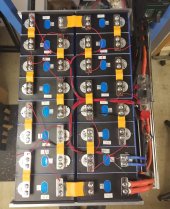
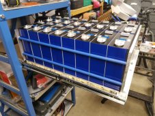
I should hopefully be assembling my 16S pack this weekend, can someone check I've worked this out correctly please?
The cells are in two rows of 8.
I'm using 1/4" Poron foam (86375K234) each end, so two pieces of foam.
I have 9 sheets of 1mm thick G10 for between cells/end plates.
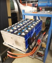
The end plates are 200 x 386 x 10mm aluminium
8 cells measure 573mm (I'll recheck this)
The 9 sheets of G10 add 9mm
Two pieces of foam is 12.7mm, 25% compression is 3.175mm, so the foam adds 9.525mm
So the gap between the two end plates should be 573+9+9.525 = 591.525mm (not that I can measure that accurately!)
Does the above seem correct?
Next question, with 10mm aluminium end plates do you think I only need 6 rods to hold it all together or go with 9 rods?
Center two rods are 6mm stainless threaded bar, outer rods are 12.7 x 3.2 aluminium tubes, tapped to take an M8 bolt.

The cells are in two rows of 8.
I'm using 1/4" Poron foam (86375K234) each end, so two pieces of foam.
I have 9 sheets of 1mm thick G10 for between cells/end plates.
The end plates are 200 x 386 x 10mm aluminium
8 cells measure 573mm (I'll recheck this)
The 9 sheets of G10 add 9mm
Two pieces of foam is 12.7mm, 25% compression is 3.175mm, so the foam adds 9.525mm
So the gap between the two end plates should be 573+9+9.525 = 591.525mm (not that I can measure that accurately!)
Does the above seem correct?
Next question, with 10mm aluminium end plates do you think I only need 6 rods to hold it all together or go with 9 rods?
Center two rods are 6mm stainless threaded bar, outer rods are 12.7 x 3.2 aluminium tubes, tapped to take an M8 bolt.

")