I think the windings around iron cores looks correct.
They will occupy more cross section where two coils cross each other. I typically see motor windings fanning out at the ends, so leave room for that.
yes sir, will make the serpentine coils long enough to be able to overlap.
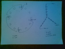
I don't follow what the red/green distinction is for magnets.
I see they alternate between red/green and green/red where I expect opposite orientation. But I expect one to have North against the stator shown, next to have South in that orientation.
that is how the magnets are oriented in a repelling orientation. a traditional orientation will have a north or south magnet pole facing the coils.
After extensive testing I am going with an iron powder filled magnet disk with a repelling orientation as shown in the schematic.
Fiberglass or other over a foam core could be one approach (like a surf board).
indeed, that is the route I am going to try. But while testing the blades I am not going to bother putting glass fiber sheets yet. Only when happy with the correct size and shape of the air foil I will start battle hardening them with glass fiber sheets and resin.
Got a CNC hot wire machine? (mill could work) Mechanical "blade" guide that changes position as workpiece fed through?
hahah I which
")
nah I found a vid on ytube, several actually, which I am going to try and replaicate
3-D printing a blade and dispensing foam into it does seem like an automated way to make many alike.
yes indeed. But it will take a few tweaks to my setup I am not willing to make just yet in fear of grinding to a halt again.
Safety wire (e.g. Monel) works very well for a hot wire cutter. Use your Variac (I think that I saw you bought one of those) to power the wire. Keep the wire slightly tensioned and increase the voltage (you might need only 10-15vac) until the wire just smokes off the oil, then fine tune from there to get good cutting without so much heat that you melt a blob out if you stop cutting.
niochrome wire is what I ordered in the meantime. Should that fail I will try Monel. thanks for the suggestion.
You are correct I have a variac in the meantime bought for the DIY transformer project.
But i've also got a switching power supply cc/cv that has a 10 amp capacity.
So we can choose between AC or DC. What would be best?
I think with the cc/cv I can configure both the voltage and the amps so that might give for better fine tuning than only playing with AC voltage.
But I could be mistaken here and suggestions welcome.
Cut the wing shape out of thin wood and glue one to each end of the foam. Now just follow the wood forms with the wire to cut out your wing.
yes sir. I'll try that!!
But why did you give up on just printing wing shapes and stacking them? A small overlap as a mortise with the next section as a tenon works very well.
well, since I am now making blades with a 40cm chord length and a 5 meter height the amount of print time and filament needed is astronomic. Even with a 1mm nozzle like I have now. For most other intricate parts I will still use 3d printing and for mold making and what not but for the blades it stopped making sense at this size. Also because it's difficult to exactly know when the filament will run out with these large prints.
Oh yeah I have also seen layer shifts for the first time ever. And I am worried that they will become more pronounced the taller the prints I am making.