diy solar

diy solar

Building the sickest ® VAWT ever. Brilliant minds unite please!!

Speaking of geometry, your design has inside corners which are right angles. Cracks will initiate there; stress is proportional to inverse of radius, and in your database the radius is zero. Needs fillets.
brother.. .. thanks again..

I am just churning out designs, not really knowing wether it is the correct way to go in broad strokes.

Once we settle on something worthwhile I will also start paying more attention to detail.
Remember my flower petals for magnet holders.

Total time spend modeling it. +- 4 hours.
Joy gained boasting about it online: infinite

hahahha. I love rambling
 
Is this going to be ground mounted, roof mounted, or up a tower ?

For ground mounted, I don't think you could go past using a car rear diff fitted with only one axle.
Mount that vertically, so the wheel flange and bearing are at the top to support the turbine on the original wheel studs.
The diff will be at the bottom, providing a very sturdy right angle drive with a speed step up ratio of perhaps about 4:1
That would hugely simplify the alternator rpm requirement.

Weld up the spider gears in the diff centre, and fill the whole thing up with oil, it should then last forever completely trouble free.

The bottom empty axle tube might be embedded fairly deep in concrete. Simple, massively strong, and cheap.

If its all going to be pole mounted, the whole pole could turn, so the alternator can be at ground level.
Its then just a case of supporting the whole thing via suitable bearings.
Maybe not at all what you want, but just a few possibilities worth mentioning.
 
Is this going to be ground mounted, roof mounted, or up a tower ?
the smaller version that should be allowed by local code will be turning on roof level. But I am not sure I'll want to connect it to the roof as I had sound issues with a horizontal turbine earlier in that location. We sleep nearby and that sound travels through the whole of the structure.

This big one I am planning now will be on a 6 meter pole in the lawn. super sub optimal I realize but I just want to see it turning for a while.

The bearings I have are only 50mm diam central hole. So rather tiny. it does fit my 48mm central column though. Let's see how far these bearings and rather skinny column can take us.
And who knows, I might get lucky and shoot a hole in the local code regulations and the larger turbine might end up being legal ;)
 
Last edited:
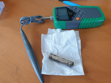
The Tesla meter has arrived. Turns out that stacking magnets does improve field strength but not at all close to a 100%

In fact both magnets individually read around 303 mT and when stacked I read 423 mT

So stacking magnets seems only usefull in very niche scenarios. geven this Lent's law I will not go that route as it will decrease power generation of the alternator.

So DD for the win it is still ;)

1660980813626.png
never mind the magnets being dirty ;) it's iron powder.
 
I will make a drawing of how I thought to make the coils after I have done the mandatory family time.

It will help shoot holes in the concept before actual winding begins
 
The Tesla meter has arrived. Turns out that stacking magnets does improve field strength but not at all close to a 100%

In fact both magnets individually read around 303 mT and when stacked I read 423 mT

So stacking magnets seems only usefull in very niche scenarios. geven this Lent's law I will not go that route as it will decrease power generation of the alternator.

Seems to me if one magnet can produce XXX mT field strength across a 1 mm gap (e.g. with a "C" shaped pole piece channeling flux from one side of magnet to within 1mm of other side), then two magnets in series could produce same XXX mT field strength across each of two 1mm gaps.

With rotating armature of magnets and stator coils on pole pieces, I think magnetic circuit would be from magnet #1, across gap, through pole piece with winding #1, forking through pole piece and back through fingers of pole piece through winding #2A (separate fork through winding #99A), across gap to magnet #2 (parallel path to magnet #99), through those magnets, across gap to pole piece with winding #2B (and #99B), reverse fork through pole piece and winding #1B, across gap back to magnet #1.

Maybe stacked magnets in rotor will help with larger gaps.

When you measured field near a stacked pair of magnets, they saw larger "gap" out North of one magnet, back twice as far past other magnet before curving into it's South. Fringing field significant compared to stack height. If you kept stacking, maybe field would asymptotically approach a particular value. Or, approach a line of Tesla/number_of_magnets. But difficult to relate to generator design with fixed gap. Need a pole piece completing circuit for more relevant measurement.
 
That all sounds quite logical and reasonable.

From the economic and practical aspect, building a larger diameter machine with twice as many poles might make better use of the magnets than doubling up on magnets on a smaller machine with fewer poles.

Twice as many poles also means fewer turns per pole required to reach target voltage.
The real killer problem here is going to be the very low rpm achievable from direct drive.
 
Magnetic components around the rim of a turbine would have much higher velocity (lower magnetic force required) compared to putting them at the hub.

How to accomplish that effectively is the puzzle. Mag Lev? Roller skate wheels running in a track?
 
That all sounds very good, and at only 60 rpm too.
How did you calculate that 58.6 volts ?
Is it between the star point and one phase, or a calculated final phase to phase voltage ?
 
That all sounds very good, and at only 60 rpm too.
How did you calculate that 58.6 volts ?
Is it between the star point and one phase, or a calculated final phase to phase voltage ?
ok, here goes.

lets take 243 millivolt as an untrustworthy value at 60 rpm while using a 9 wind coil at a distance of 1.9mm from the magnets.

DISCLAIMER: if this all above here was scientifically sound then I would have already been called by NASA. No phone call happened yet ;(

--- rant start
Anyway this is what I have to the best of my abilities and I have even allowed for peer reviews on my cost. No one came to my rescue ;( So screw all of you :) ... I am going with my data ;)
--- rant over
;)

so if 9 winds produce 243 mv at 60 rpm then by my humble logic that means.

243 / 9 = 27 mv per wind.

target voltage = 58.6 = 5860 mv / 27 =
217.0370370.......

divided by the amount of coils we can have .. / 192

1.1304012345679012345679012345679

of syntax error. I am going way overboard.

pulling the fire gun, calling all distress signals.

someone help me out here please
 
totally off topic !!

But let me tell you what I believe!

Some of those reading here realized I am of good nature, and then send that assessment to others from other fora.

And low and behold. I just got no longer banned.

All I can say is 2 things.

1) thank you! to the powers that be!!
2) really silly that I got banned in the first place.

love you all and let the rambling continue ;)
Please ramble away. I for one enjoy it.
 
You are definitely on the right track with this.
The important thing is the figures are realistic, and you will have plenty of voltage with the rpm, with the number of turns, and number of poles.

A couple of things to think about.
Under load the voltage will fall slightly, and you will lose a couple of volts across the six rectifier diodes.

On the other hand, your meter is measuring rms voltage, but a three phase rectifier puts out pretty much full peak voltage or about x1.4 what you are measuring.
Also connecting three windings in star configuration increases that by a further x1.7

So 58 volts rms measured across one whole complete set of windings, is actually 81.2 volts peak. connecting three windings in star gives 138 volts phase to phase.
That will be more than double the 58 anticipated final dc voltage.
That will fall slightly under load, but you should be able to easily reach 58.6 volts dc output at about about HALF the rpm (or lower) you are testing at now, once its all finished and working.

Less rpm is good, it means a larger and safer rotor diameter will be possible.

Don't let the math scare you, we can help with that.
But this is all going to work really well, so keep going !!
 
Last edited:
With rotating armature of magnets and stator coils on pole pieces, I think magnetic circuit would be from magnet #1, across gap, through pole piece with winding #1, forking through pole piece and back through fingers of pole piece through winding #2A (separate fork through winding #99A), across gap to magnet #2 (parallel path to magnet #99), through those magnets, across gap to pole piece with winding #2B (and #99B), reverse fork through pole piece and winding #1B, across gap back to magnet #1.
ok, I found some time to read back. Please elaborate.. what is a 'pole piece'?

All I know is that I have magnetic field directions ( poles ) and I have coils. rotating poles over the coils at a given rpm gives a certain voltage. the lentz law if I am not mistaken.
 
How to accomplish that effectively is the puzzle. Mag Lev? Roller skate wheels running in a track?
interesting question. I must admit though that since I am trying to back track posts while the BBQ needs to be lit is not ideal ;( So not sure I can figure this out in my short window of time I have left ;(
 
ok, here goes.

lets take 243 millivolt as an untrustworthy value at 60 rpm while using a 9 wind coil at a distance of 1.9mm from the magnets.

DISCLAIMER: if this all above here was scientifically sound then I would have already been called by NASA. No phone call happened yet ;(

--- rant start
Anyway this is what I have to the best of my abilities and I have even allowed for peer reviews on my cost. No one came to my rescue ;( So screw all of you :) ... I am going with my data ;)
--- rant over
;)

so if 9 winds produce 243 mv at 60 rpm then by my humble logic that means.

243 / 9 = 27 mv per wind.

target voltage = 58.6 = 5860 mv / 27 =
217.0370370.......

divided by the amount of coils we can have .. / 192

1.1304012345679012345679012345679

of syntax error. I am going way overboard.

pulling the fire gun, calling all distress signals.

someone help me out here please
I found my original post on fieldlines in where I was barely able to make sense.
Code:
"I have some encouraging results.

I wound a single coil with 9 winds and spun the magnets at +- 60 rpm under it.

I am getting millivolt readings up to 134. These values serve as indicator only, not scientifically taken.

Now if the following math is applicable then I calculate I'll be needing to wind the following coils.

0.134 / 9 = 0.0148 volts per wind per coil.

target voltage 58.4 / 96 coils per phase (48 on each side per phase) = 0.608 volt per coil.

0.608 / 0.0148 = 41 winds per coil.

Now obviously I am not taking into account the law of diminishing returns as the winds get further and further from the magnets the more winds we wind. But with a target of 41 winds we can stay well within 4mm of the magnets. The area where my readings tell me that a repelling arrangement gives us more flux to play with than with a traditional arrangement.

Also not taking into account yet what will happen if the coils are swimming in 95% iron powder resin.

Does this make sense?"
 
Back
Top