diy solar

diy solar

Building the sickest ® VAWT ever. Brilliant minds unite please!!

That is a fair bit of wind you have there !

No real problem starting with just the alternator, make it a reasonable size, and many factors should take care of themselves. It only gets really difficult when you are trying to make something really small and light weight to operate at high rpm.

Put it all together and do some testing.
You will need something powerful enough to run it up to various speeds under load, a tachometer to measure rpm (e-bay), something to measure torque with, and a suitable adjustable electrical load along with voltage and current measurement.
Its then possible to measure all of the electrical/mechanical characteristics of your new alternator.
Any changes or improvements will show up pretty plainly.
 
My question is however: why do you need it? If you build this in something like SolidWorks,
at first glance at solidworks. it is just another means of modeling is it? Or did I miss some aspect in where it can be used to calculate turbine performance like Qblade does?
btw. I abandoned Qblade as it is far above my intellect and the support forum seems to be not willing to answer my questions.

I am not entirely sure I cought your intend fully, but I am not sure you are also mentioning solidity. Swept area I am certain most of our readers are familiar with by now.
It's the solidity I am so frustrated with at the moment.
Let me give you an example of how to turn my brain into pulp.
I could go on for days with the same technobable as a result.

Now I am not suggesting all of these papers are wooly. I am just warning everyone that they might be.
 
ugg, I meant size for the alternator is not of issue.
The turbine size I am building now is an issue. I am sure that once it is spinning then sooner or later the municipality will tell me to tear it down.

The size constraints I have for the turbine, as laid out in the province rules, are a max diameter of 2m.
Now I can already shoot holes in that far too slimsy rule. It's because turbines are a fairly new concept in terms of legislation and as such are still very poorly defined.

Fear not though. I am going full force at those rules and see if I can bend the rules and/or help redefine them in favor of power generation abilities.
 
O/k so you want to do direct drive, which is entirely possible, provided the power level is not really high.
It just makes things a bit more restrictive designing the alternator, because the flexibility with adjusting alternator drive rpm is no longer there.

With Lenze's law, voltage is proportional to velocity x turns x flux density.
Diameter and flux density are not really possible to change once its built, and rpm has to be in a fairly small window with direct drive.
The only variable left to us is the turns and the number of poles. Wire gauge is fixed by the required full load current.

So you could run it with just one coil on one pole at the required rpm and see what voltage you get from it.
Just multiply that by the total number of series coils in each phase to work out what a full compliment of coils would produce.

Also, if you plan for say 100 rpm (at 6metres per second) that would be 100/60 turns per second = 1.67

A very rough estimate of turbine peripheral speed might be a circumference of 6 metres/sec divided by 1.67 = 3.6 metres.
turbine diameter 3.6/3.142 = 1.14 metres in diameter.

If you go any larger in diameter, you will not be able to reach 100 rpm at 6 metres/sec, and the alternator voltage will be lower. Good for the turbine, but more difficult for the alternator.
None of this can be worked out precisely, but a rough as guts initial guestimate of where this is all heading is better than nothing, at this very early stage.
 
All you can do is use the best magnets and keep any air gaps absolutely minimal.
it will become a trade off between;
* keeping the air gap minimum. reducing the heat dissipation capabilities of the structure.
* increasing heat dissipation capabilities of the structure. Increasing air gap.

However, since prototyping .
Sure we can improve on the usage of PLA.
But let's not forget we can also make use of high temp magnets. Sure I will not consider those for the time being as this whole endeavor is meant to be reproducible.
High temp magnets are freakishly expensive.
 
I would be very surprised if cooling is ever going to be an issue.
The magnets themselves do not get hot, only the windings get hot.
If the whole thing is running under considerable load, there should be PLENTY of cooling air roaring past at the same time.
Just keep the current density in the wire within reason, and nothing should overheat.

Air gap is absolutely critical.
Permiability of steel and cast iron is roughly 1,000 compared to air. Perhaps a tiny bit more.

In the whole magnetic path length, one miserable extra mm of air has the same resistance to magnetic flow as a whole metre of extra steel !!
So keep those air gaps absolutely tiny.
That requires good quality bearings and the rotor must run absolutely true without wobble or end play.
 
For a vertical axis machine, if you made a very low height prototype just for testing, making it taller should just increase the torque proportionally, or almost so.
yes sir, I plan to make blade sections of 1 meter each. LEGO^200^354 :)
The diameter, blade profile and number of blades should behave pretty similarly otherwise.
This is my whole conundrum. I have no evidence and / or intuition yet that tells me that is correct.
I am leaning the other way as of now.
 
So keep those air gaps absolutely tiny.
That requires good quality bearings and the rotor must run absolutely true without wobble or end play.
yes sir, I'll focus on it.

however as this is an noncommercial post apocalyptic project. I will allow for some leeway

that is not to say I will not figure out some way to blow ones socks off ;)
 
With your configuration, pancake magnet and coils, you can use shims to space them further apart. Adjust to where they don't hit even with flexing, but as close as possible.

I don't think you have any iron, steel, or ferrite inside coils yet, which would have a gap to magnets. You have a gap between loops of copper wire and magnets. Not sure which direction windings will be deflected by magnetic fields, but at higher current they will need to be secured. Encapsulation in varnish is common.

I think windings should be around cores/laminations with high magnetic permeability. Small gap from those to magnets. Gap between fingers of cores (spacing between windings on one vs. the next) are not a problem, just reduce the size of core and winding thickness, a linear reduction in capacity. But air gaps in magnetic circuit massively reduce performance.

Lack of core in windings means that air gap is from one magnet, through the coil, around the back, through another coil, to next magnet. Very long gap, massively reducing performance.
 
iron powder is great of enhancing mag field paths. It's also great for heat dissipation. But since there is still some resin to be found there there is not much movement to be had in the coils to begin with. Thus less heat.

all in all I am thinking socks will be blown. does one concur?
 
i plan to engulf the coils in +95% iron powder resin. Would that make sense?

I think magnetic materials should be used through center of windings. Not between or over outside of windings.
So I would wind coil on (or slip over) magnetic core, then encapsulate wires with non-magnetic materials.

Prior to encapsulation I think you can do open-circuit voltage tests. Tests drawing current at some level would apply a force which could deform wire. You may be able to calculate (or more simply measure a single loop driven by DC supply) to determine safe current when not encapsulated.
All EXCELLENT advice, Hedges definitely knows his stuff.

Build your rotating hub, bearings, and pole pieces, then just wind one single coil and test that first.
Compare the measured voltage with what you know you will need, taking into account the required operating rpm and number of poles.

If you cannot reach your target voltage, either the rpm will need to be increased, or it will require a larger diameter rotor with more poles and magnets.
 
All EXCELLENT advice, Hedges definitely knows his stuff.
agreed, Hedges has been helping me out since I got here. totally clueless I was back then.
Look at his message count ;) +95% of those are good advice. I'd start giving that man a 401k and a well paid job if I was in charge here ;)

Anyway I'll be diving into details of what has been said a bit later on.
 
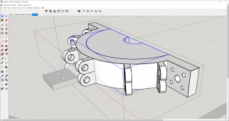
this is what I meant with an adaptive column approach ( even though I cal it that for the first time ;) )

1660896353734.png

So the central column can be up to 200mm in diameter. In my current case my central column is 48mm. yea I know not strong enough for a 4x5m turbine. But even if it only spins like 5 rotations and churns out usable data before the column buckles I am still happy.

The blue highlighted part is what I call an adapter. Between the connector and the column of one's choice.

Ok agreed, that when one needs a column wider than 200mm one has to start over. But I think in that scenario we are no longer talking DIY / post apocaliptic. If one needs more than 200mm column diam then I think it's time for them to take things more industrial. Not at all a DIY nature.

fear not though. On the side I am already pondering how we can use 3d print technology to aid in aluminum / steel casting.
Or maybe @curiouscarbon or @justgary know of a filament that can be used with high tensile stress in mind.

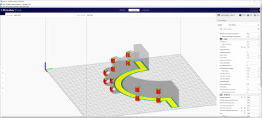
Also boys, please see my latest frustration come to manifestation.

1660896851221.png

This STL export is going no where really fast. and I don't want to now also have to debug gcode. grr my plate is like bursting already at 120% capacity
 
this is what I meant with an adaptive column approach ( even though I cal it that for the first time ;) )

View attachment 107545

So the central column can be up to 200mm in diameter. In my current case my central column is 48mm. yea I know not strong enough for a 4x5m turbine. But even if it only spins like 5 rotations and churns out usable data before the column buckles I am still happy.

The blue highlighted part is what I call an adapter. Between the connector and the column of one's choice.

Ok agreed, that when one needs a column wider than 200mm one has to start over. But I think in that scenario we are no longer talking DIY / post apocaliptic. If one needs more than 200mm column diam then I think it's time for them to take things more industrial. Not at all a DIY nature.

fear not though. On the side I am already pondering how we can use 3d print technology to aid in aluminum / steel casting.
Or maybe @curiouscarbon or @justgary know of a filament that can be used with high tensile stress in mind.

Also boys, please see my latest frustration come to manifestation.

View attachment 107546

This STL export is going no where really fast. and I don't want to now also have to debug gcode. grr my plate is like bursting already at 120% capacity
I forgot to mention that rather than printing ffrom the get go a 120 degree design (3 blades) I opted to keep in mind having to go to a 6 blade turbine. That is why you see a 60 degree hookup points rather than only at 120 degree
 
On the side I am already pondering how we can use 3d print technology to aid in aluminum / steel casting.

Early 3D printing in the 1980's used UV cure epoxy. A platform was lowered into a tank of liquid while light printed pattern on top. The result was brittle, OK mostly for show, but could be used as pattern for a mold like plaster or other material used for casting. One approach allowed injection molding.

Silicone molds can be used for some metal casting.

Cast metal doesn't always give the strength you want. Some of the guys have PV array ground mounts with cast aluminum joints and set screws to hold pipes. They have had castings crack. The alloy will matter, also geometry (which is important for plastic or anything else too.)

Machining or forging of metal parts is sometimes the way to achieve very high strength. But for the ultimate, grow single-crystal:


Speaking of geometry, your design has inside corners which are right angles. Cracks will initiate there; stress is proportional to inverse of radius, and in your database the radius is zero. Needs fillets.

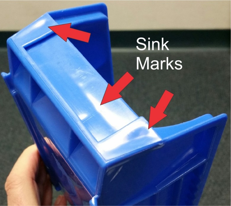
Features on one face of a cast part affect opposite face, unlike for additive or subtractive processes. See "sink marks". Perhaps that is only an aesthetic issue.

https://studiored.com/injection-molded-part-design-part-3-bosses/


5-hole pattern where the halves bolt together - difficult to fit bolts into the holes closest to column.
 
is it clear to everyone that I could use some suggestions at the moment?

WOW, this message got way disordered. it now looks as if there were many suggestions and I kept asking for suggestions as if non came.
@everone. please understand that this software, although widely used, has not ever been tested against any topic this Sick (r)
hahhhah ;)
 
Last edited:
Back
Top