diy solar

diy solar

Building the sickest ® VAWT ever. Brilliant minds unite please!!

Nah, too much on my plate. You haven't seen my garage with unfinished projects piled floor to ceiling.
But I can comment on your test setups and results.
understood brother. thank you for giving finality.

I'll keep the offer open to anyone that comes along willing and able
 
Ok buttocks back in the NL now. No more sand to be found ;(

Regarding the DD.
I think I'll do some more realistic testing first, as I had some time on the beach to ponder where I might have let bias slip in. Should my results be still the same then I'll publish them again. But this time more elaborate of course including more details on the test rig used etc.
Should I found where I went overboard I'll also share that.

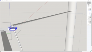
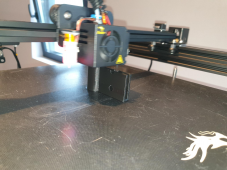
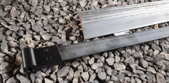
Regarding the turbine. I am now printing a holder for the 40x4 steel strips between the column and the blades.

1660732589758.png

1660732664986.png

never mind it is still PLA. this is prototyping.

once things are looking good then we can up our game to better filaments and / or post processing.
 
hahhaaha. while I am waiting for my second Tesla meter to arrive (the first one I had to send back under warranty because it stopped working)

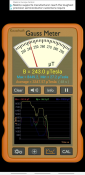
So that I can measure the merit of the stacking of the magnets in a traditional arrangement like I mentioned earlier. I found that one should never underestimate the sensors on flagship smartphones. However old they might be.
I am still daily driving a Samsung note 9 which, as it turns out to be, has a magnetometer.

Please ignore the add at the top, I am too lazy to edit that out at the moment.

1660734073556.png

Now no where as useful and accurate as the meters that is coming, and I had earlier, it will still be useful for indicators if a certain arrangement has any merit or not.
 
I am constructing small parts that will fit together like a kit, rather than large monolithic parts.
That will make it easier to improve the strength of parts where needed, and also much easier to adapt to different column diameters one might need. For example Although my current column in 48mm diam. I already know that that is not wide enough. But for quick prototyping it should be ok.

Sure it will increase the assembly efforts and usage of bolts and nuts and what have we but that is a small price to pay.

So if I make the column connector for a 200mm diam column, all one needs to to then is print adapters between the connector and the column to fit one's needs.

It's like LEGO on steroids. ;)
 
@upnorthandpersonal @Warpspeed @anyone that knows a thing or 2 about (vertical axis) wind turbines.

My biggest complaint in this field is that I can't find any data to help out people like me. (poor math skills and only looking to design something that is easy to reproduce for anyone, not caring all too much about whether it is the absolute most efficient design ever)

I even got so frustrated when repeated questions regarding what should be simple for people in the know, in various forms, went no where on fieldlines.

I got banned there, probably for calling this wooly science out. I mean there was literately no one willing and/or able to help out on the solidity aspect.

Solidity in this context means how much area the blades have in relation to the swept area of the turbine.
Sure I settled on 20cm after a phone call with one of them, a Dutchman like me, but he never posted it online. And now that my diamater has doubled (from 2 to 4m) I am left with the same damned question.

No wonder that this field has such a bad reputation if all one can find are wooly, incomprehensible studies that may or may not be worth anything.

btw the term wooly I use to describe intentional complex speak to disquice bullocks.

So if there is anyone that knows of a resource that can explain the relationship between blade area in the contaxt of swept area in newb terms. please share.
 
intentional complex speak

That's the 'problem' with research: papers are written with a target audience in mind, and in this case, it's other researchers in the area - and they assume a level of understanding (including the math and terms) relevant in the field. This is the same in my fields like cryptography and nuclear radiation. Outsiders might think it's intentionally obtuse, but it really isn't.

The thing is: do do this properly, you have to master the math that makes it work. That's why for example people on forums on radiation detection don't respond well to people who don't grasp the physics and math behind it - no matter what idea you have for a new detector. With the current climate on scientific indifference and 'who needs experts' mentalities, or just general disregard for basic science in favor of opinion (especially in online forums and communities, including this one at times) I don't blame them.

We had people on this forum come in wanting to build some complex system without even a modicum of interest in learning the math in order to do a basic power audit, or complete disregard for the use of correct units, mixing Watts, Amp Hours, Watt Hours, etc. like no tomorrow - who then get angry at you for pointing out that units matter. It gets really tiring, real fast.

Ok, this became more of a rant... sorry, back on topic.

how much area the blades have in relation to the swept area of the turbine

The swept area of a vertical-axis wind turbine:

A = π d h

Where d = diameter of the rotor and h = height of the rotor

If you design a rotor based on the above (let's call it a design goal since you want to maximize this), you get a swept area for a 4 meter turbine (let's assume 2 meter high) of:

A = 25m² or thereabout.

The area of the blades is directly related to this, but depends on if you have two, three or more blades.
My question is however: why do you need it? If you build this in something like SolidWorks, this is not independent of the overall design of your swept area. What I mean is: the swept area, together with the choice of amount of blades, drives the area of the blades.
 
anyway gang.

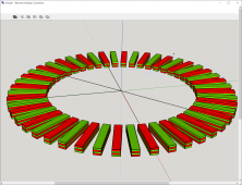
let's consider the stacked arrangement for a while.

1660743624159.png

Please forgive me if I am mistaken.
But I have seen a formula, but I have misplaced the video explaining it so I can't reference it anymore in great detail.

it goes something along these lines;
e (voltage) = b (mag field strength) * n (number of coil winds) * f (frequency for field reversal)
DISCLAIMER: the above formula is from the top of mind as I can't find the source as of now yet.

Let's assume the formula is correct for now. Also let's assume that stacking the magnets will (almost) double the field strength.

In that case the DD is noting more than a novelty. Interesting sure, a waste of time even more sure ;)

Because even though we have now only 48 poles, rather than 96, we end up with more space for coils. And I could print this disk in a single run if I wanted to.

However I already have concluded that I should always print in at least 2 parts so that it is easy to take apart a broken element that needs updating.
 
That's the 'problem' with research: papers are written with a target audience in mind, and in this case, it's other researchers in the area - and they assume a level of understanding (including the math and terms) relevant in the field. This is the same in my fields like cryptography and nuclear radiation. Outsiders might think it's intentionally obtuse, but it really isn't.

The thing is: do do this properly, you have to master the math that makes it work. That's why for example people on forums on radiation detection don't respond well to people who don't grasp the physics and math behind it - no matter what idea you have for a new detector. With the current climate on scientific indifference and 'who needs experts' mentalities, or just general disregard for basic science in favor of opinion (especially in online forums and communities, including this one at times) I don't blame them.

We had people on this forum come in wanting to build some complex system without even a modicum of interest in learning the math in order to do a basic power audit, or complete disregard for the use of correct units, mixing Watts, Amp Hours, Watt Hours, etc. like no tomorrow - who then get angry at you for pointing out that units matter. It gets really tiring, real fast.

Ok, this became more of a rant... sorry, back on topic.


The swept area of a vertical-axis wind turbine:

A = π d h

Where d = diameter of the rotor and h = height of the rotor

If you design a rotor based on the above (let's call it a design goal since you want to maximize this), you get a swept area for a 4 meter turbine (let's assume 2 meter high) of:

A = 25m² or thereabout.

The area of the blades is directly related to this, but depends on if you have two, three or more blades.
My question is however: why do you need it? If you build this in something like SolidWorks, this is not independent of the overall design of your swept area. What I mean is: the swept area, together with the choice of amount of blades, drives the area of the blades.
thank you for elaborating, and also having some patience.

Before I dive into solidworks, of which I have no current knowledge. Please allow me to give you an extreme thought experiment.

Lets consider the original 2m diam, 20cm chord length, blade count 3.
Let's assume that is indeed a wise chord length as it was suggested via phone call by someone seemingly in the know.

Now let's make the diameter 10 times bigger. a 20 meter diam.
My intuition tells me that the area of the blades, still at 20 cm chord length, can't even start rotating due to gravity drag alone.
We'll need a large blade area for that, or more blades with the same area.

My question is how can laymen like my self find out what is close to something that can work. Ignoring all the difficult details that are important to make a turbine that is the most efficient ever.
Please remember we are making the sickest turbine ever ;) that also means anyone can build it.
 
My question is however: why do you need it? If you build this in something like SolidWorks, this is not independent of the overall design of your swept area. What I mean is: the swept area, together with the choice of amount of blades, drives the area of the blades.
I need it because there seems no way around it from where I see things as of now.
Given my though experiment I presented above and the fact that there are research papaers to be found regarding solidity that makes me VERY confident at the moment we all need it!
 
ok crew, fear not

Since I have doubled the diam. I call for a vote of interest.
Who of my dear readers are interested to see if doubling the chord length, along with the turbine diam. makes a difference?

I'll give it a week. and if no signs of interest are given then I will accept that I have been talking into a void for the most part, with exceptions of course.
 
religion.

politics.


those are the subjects I would like to never been spoken about again.

Even though the whole of the USA already knows I love then, depend on them.
I assert my right to tell them I'd like them to join the metric team
 
Last edited:
I think longer blade needs wider and thicker blade, if only for mechanical strength.
Not so sure having solid area a large percentage of swept area is so important.
Hub of course gets larger for larger blade.

Tip of blades may approach speed of sound. Larger diameter means lower RPM and longer time before one blade reaches where next blade used to be. So at some point more blades may be needed to keep wind from passing through without interaction. But, jumbo-jet sized 2 and 3 blade turbines exist. We're gonna need a bigger 3-D printer!

(Why don't you make those blades 6 feet long? ;) )
 
I think longer blade needs wider and thicker blade, if only for mechanical strength.
you know what? since your intuition aligns with mine (and how ever difficult you might be to understand you do tend up nailing it most of the time) I say that from now on and further. No more reference shall be made to wooly science.

no, only gut feeling followed up with demonstration is all I care about going from here on forth.
 
(Why don't you make those blades 6 feet long? ;) )
could I make them 6 quarters of 3 4ths? ;)

anyway gang. the story continues

I just called again this authoritative country man of mine. I explained him I got banned.

Somehow I needed to remind him he told me on our initial phone call he wanted to stay updated.

Fear not though, he changed his mind. Now he is no longer interested in progress.

......

......

what can I say? why are there forces against progress?
 
What you are attempting to do is overall fairly complex, and I don't think you are going to find one very simple formula that is going to provide you with a complete final overall design of guaranteed efficiency.

I live in the suburbs, so any kind of wind turbine here would be neither socially acceptable, or practical from the high turbulence created by surrounding large trees and buildings. But I can speculate from the safety of my armchair, how I might tackle a project like this myself.

The way I would approach something like this, would be to first monitor the wind site and get some idea of the "normal" expected daily range of wind speeds.
Next step would be to estimate what might be a useful amount of electrical power to aim for, being entirely realistic.

Then I would start researching what equipment may be commercially available, and what other home fabricators have achieved in a similarly sized unit operating in similar wind conditions.

That might give you a fairly rough estimate of required size, even if some of the finer details are still a bit foggy.

From there its a case of building an initial prototype and doing some testing.
If wind speed, turbine rpm, and developed shaft torque are all measured, its then possible to calculate the developed horsepower available at different wind speeds and various degrees of mechanical loading.

Next step would be the electrical alternator. Now knowing very roughly the power capability of the wind turbine, we decide on a system voltage and current. The current pretty much defines the wire gauge of the windings.
Now the great unknown is how fast the thing has to be turned to generate the required voltage.
Diameter, number of poles, number of turns, magnetic field strength, all effect the developed voltage versus rpm.

The reality is, that whatever you build (within reason) will be able to generate the required output voltage, but the rpm to do it may turn out to be impractically high.
So the best approach is to build something of a suitably large size, based on research, and assemble it with the best magnets, and smallest air gaps you can make, and test the result.
Unless the whole thing is ridiculously undersized, it should be capable of generating the required output voltage at a sensible rpm.

It will for sure provide enough current, provided the wire gauge in the windings is sufficient. But that was your first initial design step anyway.

Last step is designing a suitable step up gearbox to match the turbine rpm to the alternator rpm. Keep pulley diameters large and belt speeds high, and if necessary use several compound step up stages of lower ratio to achieve a suitably high final overall ratio.

So its really three separate projects that finally come together to achieve a final result.
Its just a typical engineering problem, based on research of what others have already done, plus a bit of testing and development of your own.
No magic, no secret science, just hard work perserverence, and a bit of a learning curve...
 
e (voltage) = b (mag field strength) * n (number of coil winds) * f (frequency for field reversal)

found the video explaining the formula

it was;
e = B x I x v

Anyhow, this does suggest stacking can be a better solution.
The frequency of field refersals will half yet the magnetic field will (almost) double. So things remain the same up until this point.

However there will be more space for more winds of coil. So if the forumla is correct than I see no need to keep going with repelling.
I will of course measure with an actual Tesla meter (and not my smart phone) if stacking really does double the field or not. It will be here around the 22nd of this month.
 
The way I would approach something like this, would be to first monitor the wind site and get some idea of the "normal" expected daily range of wind speeds.
yes sir, I have placed a weather station at the location where the turbine will be spinning.

On average days we are looking at 5.6 m/s. it can get much better than that though. or worse. currently only 2.9 m/s and yesterday I recorded an actual 0.0 m/s ;(

THe wind is always turbulent though so that aspect also invluenced my decision to go vertical rather than horizontal.
Next step would be to estimate what might be a useful amount of electrical power to aim for, being entirely realistic.
I made the mistake to start with the alternator rather than the turbine. So I have 96 strong magnets and I'd like to take out all they have to give.
Someone over at fieldlines told me the magnets in total have around 1200 watts. But no formula and or method of getting to that number was ever shared so I am not sure how trustworthy that number is.
Now the great unknown is how fast the thing has to be turned to generate the required voltage.
Safety is more important than power in my urban scenario. So this turbine should never spin faster than 120 rpm else risk blades becoming lawn darts.
Last step is designing a suitable step up gearbox to match the turbine rpm to the alternator rpm.
Ouch ;) that will require engineering to a higher degree ;) I'd better not go there. I hope people that would like to build a turbine like this once I have demonstrated success will forgive me not going there ;)
 
Yes indeed, the (unloaded) output voltage will be directly proportional to velocity x number of turns x flux density.
Its called Lenze's Law.

Velocity will be rpm x diameter.
Actual flux density is very difficult to quantify, so very much depends on the whole of the magnetic path, and its geometry.
All you can do is use the best magnets and keep any air gaps absolutely minimal.

There should not be more space available ! If there is, the magnetic gap has been made too large.

Thinking a bit more about the actual wind turbine.
For a vertical axis machine, if you made a very low height prototype just for testing, making it taller should just increase the torque proportionally, or almost so.
The diameter, blade profile and number of blades should behave pretty similarly otherwise.
So it should be pretty easy to experiment with something pretty simple to begin testing with.
 
Back
Top