EnsignR
New Member
- Joined
- Sep 25, 2022
- Messages
- 19

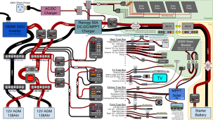
Firstly sorry for the overly, and unnecessarily complicated diagram and very long post; it's what I do.
I've been mostly lurking in this forum and elsewhere for quite a while in order to help me figure out a plan to build a new 12V system for an old van we* bought during the COVID apocalypse.
* I'm not the one who actually bought it, I'm just the one who has to figure all this stuff out. ?
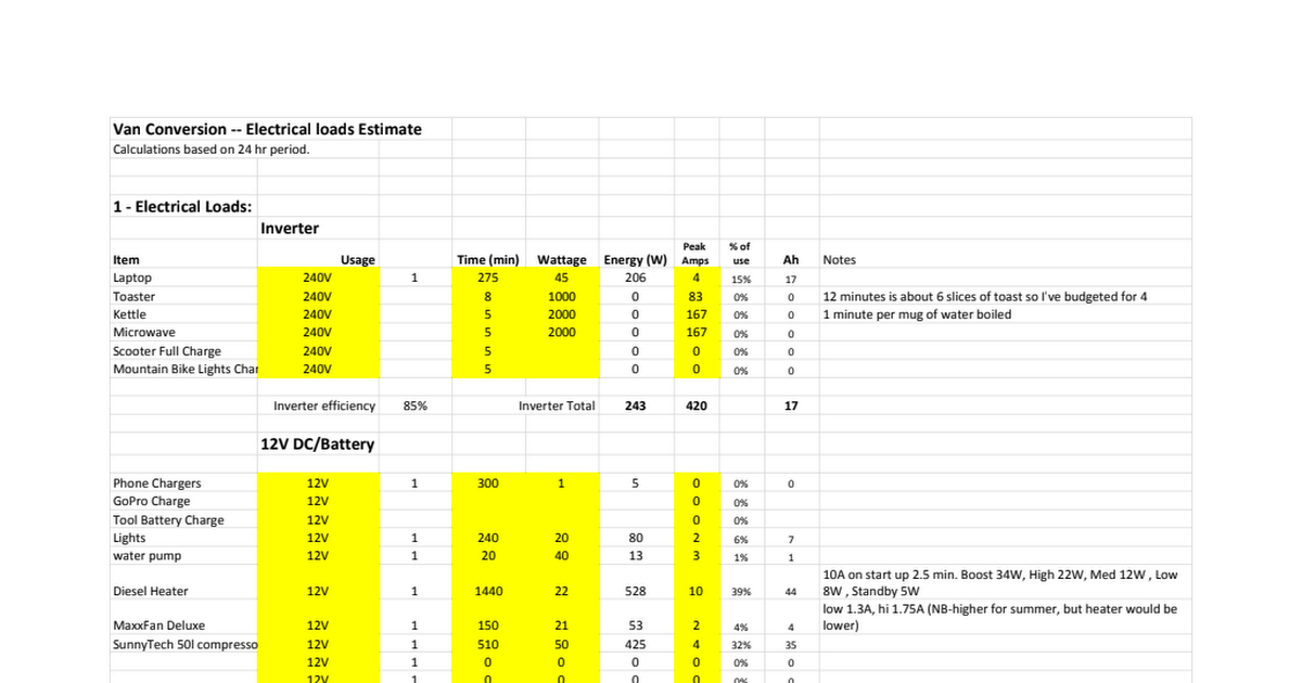
I've already temporarily installed a small system (1x 12V AGM / 20A MPPT / 200W SP), but in the long term it needs to be replaced. Currently it's mainly used to power a 12V portable fridge (not pictured; separate to the 3-way fridge, pictured, which we usually run on gas/LNG/propane) along with some lighting and occasionally a TV, as well as for charging mobile phones. It also powers the reversing camera we† installed because something is wrong with the AUX pin connection on the 7-pin trailer plug; we had an auto-electrician install it in the car but it just blows a fuse in the car if we try to use it; so we currently have to run the (house) battery while driving which isn't ideal. ?
† Of course it was actually me that installed it all. ?
The system designed above would probably need to be built in stages, but we've already bought‡ some of the parts pictured these include two new AGM batteries (which are actually identical to the one we're using now, but haven't been used), the four 4x M8 bus bars, and the inverter. Knowing what I know now I'd have built a 24V system, but the inverter is unfortunately only 12V which leaves me a bit stuck.
‡ Of course I didn't actually buy any of these, but have to figure out how to install them all; though I did suggest the bus bars after some research and thinking about how I want to do this. ?
My two main concerns are am I using the correct wire gauges for all the wires and are the circuit breakers (like these ones) or going all double pole DIN rail ones (like these); I'm leaning to the latter, but I'm really not quite sure of the pros and cons (aside from being able to mount them altogether if I use DIN)?
Wire gauges is thing I find most confusing because everywhere you look it seems to tell you didn't amperages for the same sized wire, and everything sold here (Australia) is described by cross section (mm^2). However the current, jerry rigged system is all wired together using 6mm^2, "50A", wire. My preference is to oversize the wire and not have to worry about anything catching fire. (And yes, I really am going to use twin sheath everywhere, I don't want to use the chassis as part of the circuit; am I crazy?)
The other big thing I need to decide is where I am going to put it. Currently the single battery is located at the rear of the van, under a seat. If everything fits I'd like to put most of the new system there too, but it might be a tight fit. I'm also considering putting the batteries and other bulky equipment (eg. inverter and later when I get to it, the DC-DC charger) in the boot at the front of the van (accessed from the outside). There's more room here, and would save a small fortune in running 4 AWG wire all the way to the back of the van (but then mean I have to run bigger lengths of 10 AWG to the fuse boxes). Apart from loosing valuable boot space the other problems with this is might get hotter in there and there's currently a small leak I'd have to find and fix. So many decisions.
Stage 1 would be connecting up basically the left side of the diagram; batteries, bus bars and inverter along with at least some of the separate fuse boxes (I've designed it this way as I'd rather run one 10 AWG cable than 5 thinner ones; pulling the cable will be that hardest part). The DC-DC charger and roof mounted solar, along with wiring the car with a SB120 out back, will come later.
I could go on, but I've probably written way too much already. (Sorry). Any feedback or insights from anyone would be greatly appreciated.
Cheers.
Attachments
Last edited:


 ). It can be expensive tuition. The funny thing about tuition is that whether you pay it to a formal school or the school of hard knocks, it only pays off if you use the experience to learn. (It sounds like you learned).