diy solar

diy solar

Calculation of parallel string battery currents

I discover this thread today. I have a similar concern for a 12 volt, 4P4S configuration I am building.

Given unavoidable space constraints, my 4P cell packs will be connected diagonally to each other. I know there are better ways to do this.

Like the 3P & 4P, 12v batteries in parallel analyzed above, I assume the same current sharing issues will apply to 4P cell packs within a 4P4S battery?

So, if I understand Solarod's suggestion correctly (quoted above), to try to give the parallel packs the best chance of balanced current sharing, I should be tripling the busbars (ie stack 3 on top of each other)) from parallel cell #4 to #3 adjacent to the main positive and also tripling adjacent to the 1st 4P cell main neg (btw parallel cell #1 & 2) , and so on, throughout the 4P4S pack?

I can try to draw the above if my description does not make sense.... perhaps easier in a diagram.

MP
The links labeled "3R" must have 3 times the resistance of the links labeled "R". Stacking 3 busbars will not multiply the resistance of that connection by 3; rather, the resistance of the 3 stacked busbars will be divided by 3. To do it as I described, you would have to stack 3 busbars everywhere the links are labeled "R", and only use a single busbar the two places where the links are labeled "3R".

This not-so-convenient arrangement with busbars is why I said "This method will be most practical when the links are lengths of cable rather than busbar."
Thanks for your reply Solarod. Yes, I now see that I had not read your post incorrectly and was dividing where I should be multiplying! Thanks for correcting me or I might have made things worse.

It might still be achievable with busbars if you used them with different widths ( i.e 15mm wide vs 45mm wide, assuming 15 mm provides full contact with the cell terminal). Or drill an appropriate sized hole in the bus bar (to remove some of the conductive material ) between the cells that need higher resistance. You would need to make sure the high resistance busbars had enough material left to handle your max loads...
 
I've seen comments on the forum suggesting that, given a string with load connected in the diagonal manner, there might be a benefit to making the load connections more toward the middle of the string rather than at the very corners. For the 4 battery parallel string that would be done like this:

batt2-png.89996


Setting the initial parameters back to: battery IR of 5 milliohms, link resistance of 1 milliohm, load current of 100 amps, the calculation gives this result for the theoretical battery currents in amps:

Example 8
20.8333
29.1667
29.1667
20.8333

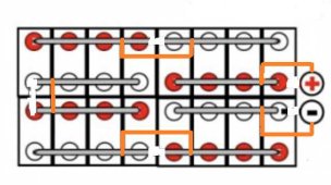
Compare this to Example 4. The values of the currents are exactly the same, but distributed among the batteries in kind of an anti-symmetric way. When I saw this, I thought "I wonder if there is a way to make a connection halfway between the two methods?". Consider the link cable between the negative terminals of battery 1 and battery 2. At a point halfway between the ends of the cable strip away an inch of insulation and expose the copper conductor. Connect the negative load cable at that point. I know this is impractical but bear with me. Now in a similar manner expose the conductor at a point halfway between the ends of the link cable connecting the positive terminals of battery 3 and battery 4; connect the positive load cable at that point. It should be as illustrated in this image:

batt3-png.89997


Now with 4 identical batteries having indentical IR of 5 milliohms, link cable resistance of 1 milliohm and load current of 100 amps the calculation shows that the battery currents in amps are:

Example 9
25.0
25.0
25.0
25.0

We have (theoretically) perfect balance! Is this a previously unknown connection giving perfect balance, like the "Halfway" connection shown in the Victron document? Does anyone know if this been published anywhere?

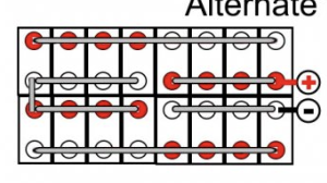
A very practical way of making this connection is possible when busbars are being used. Just drill a couple of holes at points on the busbars at the pertinent points halfway between the appropriate battery terminals and make the load connection there. This image shows what I mean:

busbar-png.89998


The usual diagonal connection would be as shown with the red and black wires. The new connection would be as shown with the yellow and blue wires.

Even more useful are the following properties. For this new connection, it doesn't matter what the battery IR is!! The calculation of the battery currents remains (theoretically) perfectly balanced for any value of IR as long as all 4 batteries have the same IR. This is very handy because as the batteries are discharged, their IR will change but this change will not upset the (theoretical) perfect balance. Also, the resistance of the links has no effect on the (theoretically) perfect balance! This means that the busbar need not be very thick copper; it can be thinner and higher resistance than would normally be needed for good balance. The only restriction is that its resistance shouldn't be so high that it gets too hot.

A mathematician would say that the (theoretically) perfect balance is invariant with respect to battery IR and link resistance. These properties are crucially dependent on the batteries having identical IR.

I expect that some reading about this may be skeptical. I was skeptical myself at first, but I've checked it several times. I invite verification by members of the community. Perhaps someone will do a simulation with Spice. The ultimate proof would be a hardware proof. If someone already has a string of 4 identical batteries in parallel with busbars, they could drill the two new holes and connect the load there, subsequently checking the balance.
U can just say … just use buss bar and your battery will be equal
 
Incorrect - he specifically said: "when busbars are being used. Just drill a couple of holes at points on the busbars at the pertinent points halfway between the appropriate battery terminals and make the load connection there"
Did you try it?
 
Thanks for your reply Solarod. Yes, I now see that I had not read your post incorrectly and was dividing where I should be multiplying! Thanks for correcting me or I might have made things worse.

It might still be achievable with busbars if you used them with different widths ( i.e 15mm wide vs 45mm wide, assuming 15 mm provides full contact with the cell terminal). Or drill an appropriate sized hole in the bus bar (to remove some of the conductive material ) between the cells that need higher resistance. You would need to make sure the high resistance busbars had enough material left to handle your max loads...
Post #4 in this long thread shows the best way to achieve (theoretical) perfect balance when busbars are being used with a parallel string of 4 batteries.. You just drill a couple of holes at the halfway point in the appropriate busbars and make the load connections there.
 
Post #4 in this long thread shows the best way to achieve (theoretical) perfect balance when busbars are being used with a parallel string of 4 batteries.. You just drill a couple of holes at the halfway point in the appropriate busbars and make the load connections there.
Solorad,

I don't think I am explaining myself well.

I am thinking about the issue of current sharing of cells in parallel in the context of a single, 4P4S battery pack, not combining batteries in parallel, as your OP contemplated.

Due to space limitations, I am stuck with a non-ideal 4P4S set up, per the image below. There are physical limitations on how bus bars can be stacked ( they must be level with each-other) so achieving 3 x resistance on the end cells of the parallel packs needs some innovation....

I am probably over thinking this and should just get some beefy (3mm x 24mm) bus bars.
 

Attachments

  • Screen Shot 2023-01-18 at 11.58.08 PM.png
    Screen Shot 2023-01-18 at 11.58.08 PM.png
    75.5 KB · Views: 28
Solorad,

I don't think I am explaining myself well.

I am thinking about the issue of current sharing of cells in parallel in the context of a single, 4P4S battery pack, not combining batteries in parallel, as your OP contemplated.

Due to space limitations, I am stuck with a non-ideal 4P4S set up, per the image below. There are physical limitations on how bus bars can be stacked ( they must be level with each-other) so achieving 3 x resistance on the end cells of the parallel packs needs some innovation....

I am probably over thinking this and should just get some beefy (3mm x 24mm) bus bars.
Have a look at posts #36, #37, #38, and #39. No matter how beefy the busbars, the clamping resistance remains a factor. Would your beefy busbars be copper or aluminum? What is the manufacturer's spec for the IR of your cells?
 
Have a look at posts #36, #37, #38, and #39. No matter how beefy the busbars, the clamping resistance remains a factor. Would your beefy busbars be copper or aluminum? What is the manufacturer's spec for the IR of your cells?
As long you such well known in batteries and electric things can we have small communication in private need to know few hint from a EE with experience
 
Post #4 in this long thread shows the best way to achieve (theoretical) perfect balance when busbars are being used with a parallel string of 4 batteries.. You just drill a couple of holes at the halfway point in the appropriate busbars and make the load connections there.
Forgot all about this thread and read it when it first came out. I'm currently assembling my battery bank with copper busbars with 4 batteries in parallel and the diagram in post #4 will be adopted. Thank you for putting this thread together.
 
As long you such well known in batteries and electric things can we have small communication in private need to know few hint from a EE with experience
I'm not the only EE on the forum. Why don't you post your questions in the General Discussion forum and then everyone can benefit from the question/answer dialog resulting?
 
Have a look at posts #36, #37, #38, and #39. No matter how beefy the busbars, the clamping resistance remains a factor. Would your beefy busbars be copper or aluminum? What is the manufacturer's spec for the IR of your cells?
Thank you for your responce Solarod.

The cells I am using are Frey or "Fortune" 100 ah cells. The IR spec is less than 1 mili ohm but in real life (from what others have reported) i think they are typically at 0.60 mil ohm. The terminals are large - 10mm with 20nm torque spec. See spec sheet attached.

The bus bars they come with are small (1.5mm by 24mm) but I plan to stack another 3mm by 25mm tinned coper on top. I am considering these for example, but quality unknown....

See: https://www.amazon.ca/TEN-HIGH-Tin-...X7S7/ref=cm_cr_arp_d_product_top?ie=UTF8&th=1
 

Attachments

  • 100ah (1).pdf
    435.6 KB · Views: 15
Thank you for your responce Solarod.

The cells I am using are Frey or "Fortune" 100 ah cells. The IR spec is less than 1 mili ohm but in real life (from what others have reported) i think they are typically at 0.60 mil ohm. The terminals are large - 10mm with 20nm torque spec. See spec sheet attached.

The bus bars they come with are small (1.5mm by 24mm) but I plan to stack another 3mm by 25mm tinned coper on top. I am considering these for example, but quality unknown....

See: https://www.amazon.ca/TEN-HIGH-Tin-...X7S7/ref=cm_cr_arp_d_product_top?ie=UTF8&th=1
If you stack the two busbars you'll have a cross sectional area of 111 mm^2, which will have a resistance of .16 microohms/mm. It looks like the distance between terminals will be 36 mm, so your resistance between terminals will be about 5.8 microohms. The clamping resistance will probably be several times that, maybe 20 microohms if great care is exercised in preparing the clamped connections, for a total resistance between terminals of 26 microohms.

If I assume the battery IR is .6 milliohms, and the busbar resistance between terminals is 6 microohms ( no clamping resistance), I calculate that the 4 theoretical currents in each subunit of 4 cells (with 100 A pack load current) in parallel would be (in a perfect world if you didn't have to worry about clamping resistance :)):

25.25 A
24.75 A
24.75 A
25.25 A

Including the clamping resistance for a total resistance between terminals of 26 microohms, the currents would be:

26.04 A
23.96 A
23.96 A
26.04 A

If you stacked another busbar, the total busbar resistance would be about 3.6 microohms, but the clampling resistance would be the limiting factor. And, I suspect that a clamping resistance of 20 microohms may be excessively optimistic.

I think I see how you could use some short lengths of heavy cable to implement the halfway connections shown in post #4 of this thread, but you might find the balance acceptable without doing that.
Thank you Solarod!

Wonderful that the forum has such a resource.

I was concerned that at a cell IR of 0.6m ohms, I would end up in an imbalance similar to example # 6 (i.e : 42, 8, 8, 42 amps). But the short, low resistance busbars seem to help. If I can keep it with a 20% imbalance, that seems reasonable. Presumably when charged, the parallel cells should rebalance themselves as they get into the upper knees of the charge cycle.

Also, I take RCinFLA's point of cell resistance increasing with loading. I assume the thing to do hear is to test the cells under load ( .5C?) and sort and place the lower resistance cells into the middle positions of the 4P packs?

My other option (with the same cell layout) would be to run two 2P4S packs, but that would mean two BMSs and my whole system analog relays ( and not a FET based BMS) so this would be a real pain to set up and monitor....
 
Here's how you could implement the half-way connection from post #4:

4p4s-jpg.130582


The orange connections would be made by short cables.

It would probably work best if the busbars were all one piece with 4 holes connecting the 4 terminals of one 4P string. Drilling a fifth hole would give the place to connect the short cables.

One of the beauties of the half-way connection is that the balance is (theoretically) perfect no matter what the resistance of the busbars or the IR of the batteries (as long as they track with temperature and SOC), so you don't need the busbars to be "beefy". The only restriction is that the resistance of the busbars can't be so high that they get hot. For example, a 1 milliohm length of busbar carrying 100 amps will be dissipating 10 watts. If you had something like 24 links in your battery, you would be dissipating over 100 watts on the top of your battery; you could keep your dinner warm!

You could use the busbars that come with the batteries, but you'd have to overlap at each battery terminal. I think it would be better to use busbar sections long enough to span 4 batteries.
 

Attachments

  • 4P4S.jpg
    4P4S.jpg
    25.1 KB · Views: 130
Here's how you could implement the half-way connection from post #4:

4p4s-jpg.130582


The orange connections would be made by short cables.

It would probably work best if the busbars were all one piece with 4 holes connecting the 4 terminals of one 4P string. Drilling a fifth hole would give the place to connect the short cables.

One of the beauties of the half-way connection is that the balance is (theoretically) perfect no matter what the resistance of the busbars or the IR of the batteries (as long as they track with temperature and SOC), so you don't need the busbars to be "beefy". The only restriction is that the resistance of the busbars can't be so high that they get hot. For example, a 1 milliohm length of busbar carrying 100 amps will be dissipating 10 watts. If you had something like 24 links in your battery, you would be dissipating over 100 watts on the top of your battery; you could keep your dinner warm!

You could use the busbars that come with the batteries, but you'd have to overlap at each battery terminal. I think it would be better to use busbar sections long enough to span 4 batteries.
Thank you again for considering my specific use case.

Implementing the pack connections as you illustrated above should be pretty easy. Would be good to avoid stacked & large gauge busbars with your above workaround.

Good point on the resistance of stacking busbars. I was not planing on using a series of 2 link bus bars. Luckily the manufacture (Frey) makes 2 to 6 link busbars available. See attached drawing of their busbar options. I have ordered 4 hole versions as well as some 2.

The next question is the placement of the BMS balance leads. I have a BMS that uses passive, dissipative balancing, so essentially a load. I assume the attachment points should be the same locations as the positive ends of the orange leads?

I have never quite understood how BMS balancing works. For eg. if each 4P pack was labeled #1 - 4, and if pack # 2 was high, does a passive BMS place a momentary load between the 2nd and 3rd balance leads? If so, this would be an unbalanced load for the 4P pack. However, it only balances when changing and at higher voltages, so perhaps less of an issue....Sorry, I recognize this is getting pedantic - but it's an interesting thought experiment.
 

Attachments

  • BUS BAR SIZE.pdf
    61 KB · Views: 9
You have 4 100ah cells in parallel so you could discharge as much as 800 amps and still be within the max average discharge rate for the individual cells! As I mentioned one needs to watch out for overheating the busbars.

You have the right idea about where to connect the BMS leads. As far as the operation of passive BMS goes, you understand how it works, but there's a lot of discussion of when it should kick in.

I hope you'll keep us all about how your project goes. Perhaps start a new thread and give us the full story.
 
Yes, I'll start a new thread once I get everything sorted. These are replacing 4 EVE 280 cells, so will be an interesting comparison.

Thanks again.

MP
 
Yes, I'll start a new thread once I get everything sorted. These are replacing 4 EVE 280 cells, so will be an interesting comparison.

Thanks again.

MP
I have studied your great post from beginning to end @Marinepower (sorry, I mean @Solarod )
Without being a propellerhead, I am most interested in the part about five parallel batteries (I recently added my fifth battery) with the following added twist/challenge: only two of my batteries are 100Ah factory built batteries, the other three are all DIY 280Ah batteries (all are 16S nominal 51.2voltDC).
All five batteries attach to their bus bars with equal lengths of 1AWG battery cables.
I built these into a cabinet with heavy copper bus bars for Neg, Pos, the bars are 110 copper, 50mm x 8mm and these connect mid-bus each to 4/0 welding cables that feed a smaller bus via T-class fuses and split to two inverters with equal length cables for balance.
The part I had not considered, when building this set up, I put all the 280Ah DIY batteries at the base of the cabinet (these are heavy!) and the two 100Ah racks at the top. After studying your posts, I understand this is 1) very complex to analyze 2) there is likely no perfect balance option available for five units anyway.
It seems to me, it may be better to have the two 100Ah racks in the centre of the stack, but I am not sure.
As built, the copper bus bars are 24 inches long, and the batteries are not equally spaced, the 100Ah batteries are shorter (6" tall) and thus closer together while the 280Ah batteries are taller (9-1/2" tall) and thus connections further apart. But the cables are long enough, so I could change this.
Because the batteries add up to more than the bus lengths, the bus are centred in the vertical height of the cabinet, and the highest battery's cables reach down a few inches, and the lowest battery's cables reach up a few inches to attach to the ends of the bus bars.
Recommendations?
 
Last edited:
Back
Top