diy solar

diy solar

Using solar micro inverters with batteries instead of panels

... the battery protector or another relay controlled by the battery protector was not shown in his circuit diagram...
I'm still reading from the beginning to catch up and the end to be current, but earlier there was an image showing the protector, relay, and timer. Not sure how much it's changed, but probably only those two components, breakers, and wires. He did say he had problems with the Victron, possibly it didn't have enough resistance?

Even a contactor will have resistance; datasheets for them will have something like 2.5W per pole power dissipation. Possibly there's an IR image or something in the thread, if it's hot it's got resistance (it would be funny if it worked because of a poor crimp ; -).

Update: Oops... should have read all the way to the end, seems like you've already thought of these ; -)

In my case, it’s only load-shaving I’m after and only during daylight hours.
Currently, my use case is emergency power, so the bi-directional charger and EV seem the most cost-sensible approach. But, I know it's only a matter of time before TOUs come into play and they decrease reimbursement for the power exported, so any solution for me needs to be flexible enough to handle that and Enphase seems quite capable.
 
Last edited:
it is possible that in addition to checking for shorts between positive and negative to ground as documented, the M250 also checks for resistance between positive and negative and/or seeks the two operating points it needs to begin generating power when it first receives DC current

Last night I discovered something odd w.r.t my AIO connected to the same battery bank: when AC and DC breakers are both off, DC positive (either side of breaker) and negative both show 1MOhm+ to ground.

But ~20 seconds after either AC or DC is enabled and after initial AIO bootup, my meter shows DC neg->ground fluctuating to the point it can't lock onto a value. I wonder if that noise similarly prevents the m250 from obtaining a solid resistance reading. I have an old analog scope in my storage unit, may eventually dig it out to visualize the situation.
 
A measurement of round-trip resistance as I just outlined on the prior post would be fantastic if possible but with model numbers for every inline element, we can probably make an educated guesstimate.

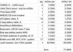
I decided to go through this itemization exercise myself to understand the role of the extra resistors I’m adding. Most values from data sheets except for the bolted connections which is a WAG.

1682700115133.jpeg

And as noted in my earlier message, there are other 24V devices operating in parallel with this m250 circuit: AIO, smartshunt, USB power adapter.
 
I decided to go through this itemization exercise myself to understand the role of the extra resistors I’m adding. Most values from data sheets except for the bolted connections which is a WAG.

View attachment 146955

And as noted in my earlier message, there are other 24V devices operating in parallel with this m250 circuit: AIO, smartshunt, USB power adapter.
Nice itemization. Is it possible to measure from the battery connection wires round-trip through shorted MC4 connectors?

Also, are those 17 bolted primarily the internal connections within the battery itself?
 
Nice itemization. Is it possible to measure from the battery connection wires round-trip through shorted MC4 connectors?

From the system side of the main battery shutoff (behind which are only the batteries and main fuse), 110mOhm. That's with main battery switch open, main breaker closed, MC4 shorted, and a wire bridging the SSR.

Also, are those 17 bolted primarily the internal connections within the battery itself?

Batteries are connected in parallel: 2xprebuilt 24V (AmpereTime/LiTime) and one pair of prebuilt 12V (Chins) - all with welded bus bars .
The 17 covers the 6 bolted external battery stud connections as well as bolts connecting cables to switch, breaker, shunts and breakers.
 
Thought I'd put together a summary regarding working/not-working setups since I'm catching up on the 14 pages, mostly it seems centered around what @agt reported:

Solid Red: For all M250 models and for M215-60-2LL-S22-IG, this indicates a “DCResistance Low – Power Off” fault....
An insulation resistance (IR) sensor in the microinverter measures the resistance between the positive and negative PV inputs to ground. If either resistance drops below a threshold, the microinverter stops power production
It was speculated that the resistance check may not be from + to -, but rather + to and - to .

In general, @kundip and others seem methodical and practical, so I imagine they're following generally good practices regarding crimps, tightening, and dielectric grease. Note this recap doesn't include some fascinating findings (e.g., @jimbob232's discovery about inductors for PWM). Despite that, it's not really clear what components are in the DC path for working versus non-working setups, or what their electrical impacts might be.

As the thread ages things change, so please don't freak out. Also paraphrased a lot of it to be concise, please correct anything I got wrong and apologies in advance:

In post #26 @newbostonconst says it works for him, he has a Victron Shunt. It's not his first rodeo, so the stuff between is probably: breakers, shunt, battery protector, BMS, relay, wire, and a bunch of crimps. Hopefully, they can confirm/deny.

In #46 @newbostonconst reports getting the DC Resistance light after reconfiguring his pack from 55 Ah to 550ah pack 20 cells 66 volts. No information on grounding.

In post #27 @kundip mentions he has a shunt. He also mentions that he has both IQ7s and M215s, which could have different detection ranges (not to mention he's at 50 Hz which was later pointed out isn't mentioned as having DC resistance checks)

In #49 @agt posted a video suggesting battery voltage over Vmpp inhibits V/A-seeking on M190s. But in post #109 @kundip shares his experience if you go over the voltage the micro shuts down.

In #52 @ericgrand reports no problems with M215 microinverters & 6 Valence U27-12XP batteries (2S-3P)

In post #59 @AntronX reports it working with a Power Supply from 14.1V to 47.8V DC input (>22V to startup) and maxes out at 10A below 25.5V.

In post #60 @markdyer reports success with m230 micros & 36v esccoter batteries

In post #64 @kundip posts photos of his system with buck converter (which he no longer recommends). Don't see thick cables from the BMS to the battery, so output power probably doesn't go through the BMS (post #136 seems to indicate it does)? In #66 he says he has 15 amp fuses, not breakers. In #68 he says he few interesting things:
  • a 24v 30amp relay (looks like an automotive mechanical rather than SSR).
  • I don't run ...current through the Victron Battery Saver ...It kept on complaining about "inrush current"
  • use the Victron to turn on and control the relay. The Victron cuts off the battery @ 24v. ???
Post #76 is from a few weeks ago and @kundip's latest design. Looks like there's no shunt, no battery protector, no breakers - just the battery and a "kaza" timer (looks a bit like a high-amp AC pool-pump mechanical timer). This is probably just an image of the AC side?? (confirmed later it is DC).

In post #80 @kundip says he is using the Power Mate battery protector, possible behind the board in #76? He also says he used high-end batteries: Amptrons or EVPower Batteries. Also has two 5 KG dry powder fire extinguishers, big thumbs up! Wonder if those are automatic or manual...not in the photos.

In post #82 there's an image of the current setup showing the AC side and partially the DC sides? A 20 amp fuse and a battery protector are marked, but can't tell if a shunt is in there or if he's still using a relay (with the AC output setup a relay on the DC side shouldn't be needed).
In addition to the 20 amp fuse on the motormate, each micro has a 10 amp fuse.

In post #136 @kundip says the timers are on the DC side, there's an image in #139 that seems to agree... but that image also has a relay before the timer? He also says the BMS can cut the battery off, so it must also be between the battery and micros on the DC side, but it's not shown in #139. His desire to be neat and tidy makes it impossible to track the wiring.

In post #154 @jimbob232 reports using PWM to throttle output was successful (I was thinking along the same lines before I decided microinverter outputs were granular enough a relay bank simplified the complexity).

In post #230 @fafrd has some experimental data with resistors, but it didn't make sense to me. In #248 he reiterates. His resistance is + to - and seems centered around stabilizing the MPPT tracking, rather than eliminating the DCResistance Low faults.

In Post #229 @agt says he was able to bypass the DC resistance check at 2.5W loss.

Profiles?
Enphase's micros are controlled by their profiles, so possibly it's the profile causing the different behaviors. Although, @newbostonconst 's experience with just switching the batteries causing failures does point more towards internal resistance.
It would be interesting if those with Envoy's could tell us what profiles work for them.
@jimbob232 reports the UK profile, but if it's like here there's probably a dozen of them.

Summary of the Summary
There's no clear diagram of a working sytem end to end. It's not always clear if the problem is the DCResistance Low or if it's a failure of MPPT tracking to lock on.
 
Last edited:
Thought I'd put together a summary regarding working/not-working setups since I'm catching up on the 14 pages, mostly it seems centered around what @agt reported:


It was speculated that the resistance check may not be from + to -, but rather + to and - to .
Great summary - I only got involved after kundips most recent posts and had never scanned back through earlier attempts / results.

And the textual description makes it quite clear that the resistance check described is checking for shorts from + to gnd or - to gnd.

I don’t believe there is any ambiguity on that. The only question is what additional undocumented checks may be getting performed or what other fault conditions might arise from insufficient resistance between + and - (more on that below).
In post #230 @fafrd has some experimental data with resistors, but it didn't make sense to me. In #248 he reiterates. His resistance is + to - and seems centered around stabilizing the MPPT tracking, rather than eliminating the DCResistance Low faults.
To clarify, the data I graphed was simulated using a simple spreadsheet model, not experimental (I have not tested anything yet).

And the resistance I simulated was an inline resistance between + and - (so adding a 0.05 Ohm power resistor inline between battery +output and Microinverter + input, for example.

I compared the slope a Microinverter MPPT will have to deal with at only 0.01 ohms of wiring resistance, 0.05 ohms total and 0.1 Ohms total.

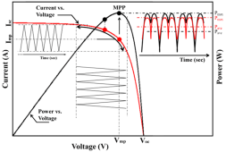
Solar panels have negative slope corresponding to roughly ~1 ohm and as the resistance gets smaller and smaller and the slope gets steeper and steeper, if becomes harder and harder for the MPPT to lock in to the second operating point…

This is what Microinverters MPPTs are designed to lock on to coming off of a solar panel: 733565C7-7361-4D93-993E-C5C81E2BE3BC.png
An infinite negative slope 0 ohm effective resistance beyond Vmp is impossible for even the best MPPT to lock on to…
In Post #229 @agt says he was able to bypass the DC resistance check at 2.5W loss.
Using a 4 ohm resistor inline.
Profiles?
Enphase's micros are controlled by their profiles, so possibly it's the profile causing the different behaviors. Although, @newbostonconst 's experience with just switching the batteries causing failures does point more towards internal resistance.
It would be interesting if those with Envoy's could tell us what profiles work for them.
@jimbob232 reports the UK profile, but if it's like here there's probably a dozen of them.

Summary of the Summary
There's no clear diagram of a working sytem end to end. It's not always clear if the problem is the DCResistance Low or if it's a failure of MPPT tracking to lock on.
From the description, DC Resistance Low is merely checking for shorts (insufficiently high resistance meaning 100s of kOhms rather than single-digit Ohms) from + to ground and from - to ground, which can’t be skirted around by merely adding a 4 ohm resistance inline.

So whether the fault condition ends up being thrown into the same fault bucket as insufficient resistance from + to ground or - to ground, there is either another undocumented resistance check from + to - that is being performed or there is another fault condition caused by the MPPT seeing lower + to - resistance than it expects or failing to lock on to needed operating points…
 
Last edited:
I want to follow-up svetz’s excellent summary with a bit of structure:

There are 3 broad architectures / circuits being pursued to power Microinverters from batteries in the recent posts of the thread:

DIRECT FROM BATTERY:

kundip has been running a direct from battery circuit for over 2 years now and the only real question we are trying to get a handle on is what effective round-trip resistance he has in that circuit and why he has had no issue with Resistance Check Fault conditions if others are unable to get a similar circuit working.

AGT also has a direct from battery circuit working but in his case, he is using a 4 Ohm inline resistance to pass the Resistance Check / MPPT Lock-on phase and switching from 4 Ohms to a 0.05 Ohms power resistor after power generation starts (and likely closer to 0.07 ohms all-in).

BATTERY THROUGH DC-DC CONVERTER:

kundip has another circuit working with a DCDC converter (buck converter in his case) which has operated for over 2 years.

I am planning to test with DCDC boosters later this year. The primary fears of using cheap DCDC converters are twofold:

1/ finicky / unreliable to configure / set (through pots). kundip was unhappy with that aspect but we don’t yet have anyone else’s results to compare).

2/ unstable current output and particularly high-frequency ripple. High-frequency ripple can heat up and eventually degrade the input capacitors of a Microinverter and so could cause premature failure. A simple passive filter, possibly including an inductor is a solution to protect input capacitors from excessive current ripple that is being pursued.

BATTERY THROUGH PWM MOTOR CONTROLLER:

jimbob32 is the pioneer on this approach and has successfully tested it using a benchtop power supply rather than a battery (so more akin to using a PWM powered by a DCDC booster than PWM powered by battery).

PWMs are appealing because of their ease of control (duty cycle) using an external potentiometer which provide for easy dynamic control from an Arduino/RPi or PLC using digital or even analog controls. But PWM output is the absolute worst-case as far as current ripple so the filtering techniques being explored including the use of inductors is primarily being driven by the PWM approach.
 
Last edited:
In general, @kundip and others seem methodical and practical, so I imagine they're following generally good practices regarding crimps, tightening, and dielectric grease. Note this recap doesn't include some fascinating findings (e.g., @jimbob232's discovery about inductors for PWM). Despite that, it's not really clear what components are in the DC path for working versus non-working setups, or what their electrical impacts might be.
I crimp & solder every joint.
No dielectric grease.
In post #27 @kundip mentions he has a shunt. He also mentions that he has both IQ7s and M215s, which could have different detection ranges (not to mention he's at 50 Hz which was later pointed out isn't mentioned as having DC resistance checks)
The EV Power came with a shunt & a reader but I disconnected the reader & I am going to take the shunt out.
I just don't use it.
I can see from the Envoy data what each battery is doing easily.
In post #64 @kundip posts photos of his system with buck converter (which he no longer recommends). Don't see thick cables from the BMS to the battery, so output power probably doesn't go through the BMS (post #136 seems to indicate it does)? In #66 he says he has 15 amp fuses, not breakers. In #68 he says he few interesting things:
  • a 24v 30amp relay (looks like an automotive mechanical rather than SSR).
  • I don't run ...current through the Victron Battery Saver ...It kept on complaining about "inrush current"
  • use the Victron to turn on and control the relay. The Victron cuts off the battery @ 24v. ???
No thick cables - just 20Amp cables.
I have explained the Victron Battery Protect setup later in this post.
Post #76 is from a few weeks ago and @kundip's latest design. Looks like there's no shunt, no battery protector, no breakers - just the battery and a "kaza" timer (looks a bit like a high-amp AC pool-pump mechanical timer). This is probably just an image of the AC side?? (confirmed later it is DC).
There is no shunt.
All my circuits have battery protectors.
I just use a 20Amp blade fuse at the battery and a 10 amp blade fuse prior to each inverter.
The Kaza timer is a 240VAC WiFi TP-Link device - it turns the charger on in the morning & switches the charger off in the afternoon.

In post #80 @kundip says he is using the Power Mate battery protector, possible behind the board in #76? He also says he used high-end batteries: Amptrons or EVPower Batteries. Also has two 5 KG dry powder fire extinguishers, big thumbs up! Wonder if those are automatic or manual...not in the photos.
The positive side has a 20Amp blade fuse near the + terminal then it goes through the MotorMate battery protector first, set at 23Volt cut off, then on to the timer.
Yes I only use high end batteries I usually pay 1/2 price for.
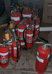
I have fire Extinguishers EVERYWHERE along with hard wired smoke detectors including where my batteries are.
Fire extinguishers are all manual.
I Probably have about 20 all up.
I get the discontinued fire extinguishers, (meant to be destroyed) that are still fully charged & the pressure needle in the green.
I turn them up once a year & hit them with a rubber mallet - 360 degrees.
I have signs on them ("For Decorative Purposes Only")(to cover my rse) but they still work perfectly.
.
1682858864024.png
In post #82 there's an image of the current setup showing the AC side and partially the DC sides? A 20 amp fuse and a battery protector are marked, but can't tell if a shunt is in there or if he's still using a relay (with the AC output setup a relay on the DC side shouldn't be needed).
In addition to the 20 amp fuse on the motormate, each micro has a 10 amp fuse.
No shunt - I don't see the point - for me.
No relay with the MotorMate.
I only used the relay on the Victrons when they kept on tripping on "Inrush Current"
The Victron's were set to kill battery supply, to the MicroInverter, at 24V via the relay.
So the main power went from the 20Amp (Blade Fuse) protected battery to the timer (&timer relay) & then on to the 24V car relay which is controlled by the Victron battery protect. The 10Amp blade fuse is just before the MicroInverter.
I have not transferred all to my new design as there have been so many questions about those other circuits.

In post #136 @kundip says the timers are on the DC side, there's an image in #139 that seems to agree... but that image also has a relay before the timer? He also says the BMS can cut the battery off, so it must also be between the battery and micros on the DC side, but it's not shown in #139. His desire to be neat and tidy makes it impossible to track the wiring.
No relays before timers.
Photographic illusion.
My new design has no relays - other than the timer.
Summary of the Summary
There's no clear diagram of a working sytem end to end. It's not always clear if the problem is the DCResistance Low or if it's a failure of MPPT tracking to lock on.
I am sorry I am so slow at getting other data back to you.
I am trying here but I am not very good at this electronic stuff.
 
I want to follow-up svetz’s excellent summary with a bit of structure:

There are 3 broad architectures / circuits being pursued to power Microinverters from batteries in the recent posts of the thread:

DIRECT FROM BATTERY:

kundip has been running a direct from battery circuit for over 2 years now and the only real question we are trying to get a handle on is what effective round-trip resistance he has in that circuit and why he has had no issue with Resistance Check Fault conditions if others are unable to get a similar circuit working.
I will try to get this reading to you.
AGT also has a direct from battery circuit working but in his case, he is using a 4 Ohm inline resistance to pass the Resistance Check / MPPT Lock-on phase and switching from 4 Ohms to a 0.05 Ohms power resistor after power generation starts (and likely closer to 0.07 ohms all-in).

BATTERY THROUGH DC-DC CONVERTER:

kundip has another circuit working with a DCDC converter (buck converter in his case) which has operated for over 2 years.
I tried another brand new boost converter - exactly the same model - but I just cannot get it to control the current.
This is the eighth time I have tried to replicate it. (5 Boost Converters the same & three other types.)
Why the first one is working I do not know.
All I can think is that the MicroInverter is controlling the current.

I am planning to test with DCDC boosters later this year. The primary fears of using cheap DCDC converters are twofold:

1/ finicky / unreliable to configure / set (through pots). kundip was unhappy with that aspect but we don’t yet have anyone else’s results to compare).
YES
2/ unstable current output and particularly high-frequency ripple. High-frequency ripple can heat up and eventually degrade the input capacitors of a Microinverter and so could cause premature failure. A simple passive filter, possibly including an inductor is a solution to protect input capacitors from excessive current ripple that is being pursued.
If a MicroInverter ever blows up I will worry about that then.
At this stage they are dirt cheap & easy to replace.
Especially compared to string Inverters - just no comparison.
The ripple is past my ability to do work on - I will keep trying to get better at this.

BATTERY THROUGH PWM MOTOR CONTROLLER:

jimbob32 is the pioneer on this approach and has successfully tested it using a benchtop power supply rather than a battery (so more akin to using a PWM powered by a DCDC booster than PWM powered by battery).

PWMs are appealing because of their ease of control (duty cycle) using an external potentiometer which provide for easy dynamic control from an Arduino/RPi or PLC using digital or even analog controls. But PWM output is the absolute worst-case as far as current ripple so the filtering techniques being explored including the use of inductors is primarily being driven by the PWM approach.
I tried a few of these but they went to hot or just burned up.
I did not use anything expensive - maybe USD$100 tops.
Again - I did not really understand what I was doing.
 
I will try to get this reading to you.
You are already my hero, but f you can read the round trip resistance from battery positive connection wire all the way to positive MC4 connector disconnected from Microinverter and shorted to negative MC4 connector (also disconnected from Microinverter) and all the way back to battery negative connection wire connection in the way I outline, you will be even more so.

All circuit elements that can inturrept connection from battery to Microinverter including timer/relay and possibly also battery protector/relay will need to be closed (tricked into connecting the battery if they otherwise would disconnect it).

The other thing you can do that would be helpful is to refine the simple wiring diagram you prepared. Every element in the paths needs to be shown. The blade fuse at the battery, the blade fuse at the Microinverter, the box which is the timer/relay, the box which is the battery protector (if the battery protector has inputs and outputs and can disconnect the battery, it also contains a relay).
I tried another brand new boost converter - exactly the same model - but I just cannot get it to control the current.
This is the eighth time I have tried to replicate it. (5 Boost Converters the same & three other types.)
Why the first one is working I do not know.
All I can think is that the MicroInverter is controlling the current.
It sounds as though you are attempting to adjust your booster while it is in the process of delivering power to the Microinverter and that is not going to work. The Microinverter is switching the voltage which causes the converter to change current which causes the Microinverter to change to different voltages, etc..,

A tiger chasing it’s take.

I’m guessing it’s pure blind luck that caused the one unit to lock on properly and begin generating power.

If you want to try again, here is the sequence to use:

Decide upon voltage to use. The minimum voltage needs to be maximum battery voltage +2 volts and the maximum voltage to use should not be much much higher than the Vmp of your solar panels. Suggest you try 30VDC to start.

Powering off of battery but not connected to Microinverter, you need to use a multimeter to measure output voltage and adjust pot until you hit your target voltage (30V).

The next phase is easiest if your multimeter can measure DC current.

You need to calculate your target output power by taking the Microinverter output you are aiming for and deciding by Microinverter efficiency. For example:

250W / 95% = 263W.

Now divide by output voltage you set:

263W / 30VDC = 8.8A. That is the current setting you are aiming for.

So now you want to connect you multimeter to read current and adjust the current pot until you read 8.8A.

If you have a 100W power resistor handy, it’s a good idea to check output using that before connecting to your Microinverter.

Connecting + and - across a 1 Ohm power resistor will put 8.8A across 1 Ohm for 8.8V of output (at 8.8A^2 x 1 Ohm = 77.4W of power). So if you put your multimeter in voltage mode and now read ~8.8V across the power resistor, you know the converter has been properly configured for 263W @ 30VDC.

You can now try connecting to your Microinverter but you need to make sure you have at least 0.05 Ohms of resistance between the booster and the Microinverter. If there is a timer relay in that path and is has over 0.5 ohms of resistance when closed/on, an additional power resistor may not be necessary, but if the timer controls DC power at the input of the booster and not the output, I’d advise you to add an 0.05 Ohm power resistor on the positive output of the booster before connecting to Microinverter.


You cannot use a power resistor above 1.3 Ohm so let’s say you are using a 1Ohm power resistor.

You can also use 0 Ohms which is a short (no power resistor) but using a 1 Ohm power resistor would be better if you have one.

So now you are going to connect through your multimeter


YES

If a MicroInverter ever blows up I will worry about that then.
At this stage they are dirt cheap & easy to replace.
Especially compared to string Inverters - just no comparison.
The ripple is past my ability to do work on - I will keep trying to get better at this.
I understand you are not worried about your Microinverters or ripple current and so that is why I am not suggesting you screw around with inductors.

My goal is to help you see whether you can successfully configure your DCDC boosters for use powering your mucroinverters without feeling they are unstable. First, you need to set the booster using a multimeter and not connected to a Microinverter as I have outlined above. And second, you need to add an 0.05 Ohm or 0.1 Ohm m 100W power resistor between booster output and Microinverter input to make it easier for your Microinverter to lock on to operating points.
I tried a few of these but they went to hot or just burned up.
I did not use anything expensive - maybe USD$100 tops.
Again - I did not really understand what I was doing.
For your use case (constant output level, simple ON / OFF control using timers and battery protectors) there is no advantage to using PWMs.

If a slightly more rigorous pot-setting methodology allows you to successfully use cheap DCDC boosters to power Microinverters and to stop feeling they are unstable or unreliable, I believe that is a more useful objective for you.
 
You are already my hero...
Mine too! I love that he has this working....

I crimp & solder every joint....
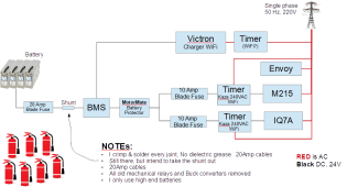
Does this look like your setup? Any thing left out or wrong?
1682888160176.png

If anyone wants the image let me know and I'll put it up on google docs or something... it was made with the free OpenOffice tools (See also Drawing Tools).
 
Last edited:
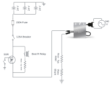
I spent time this weekend testing various values for the two resistors I'm connecting between the batteries and the m250: Rboot, connected only during m250 startup and initially 4 Ohm; and Rrun, connected at all times. The following diagram depicts the path from battery to m250:
Blank diagram (8).png
I'm tracked results of various Rboot and Rrun configurations in a Google Sheet.
My findings so far:
  • At least 260mOhm system resistance (Rboot) is required for my m250's to boot. Much less than my initial 4 Ohm!
  • Once drawing power, resistance may be dropped as low as 85mOhm (Rrun): 60mOhm from cabling/etc, 25mOhm power resistor
  • Inverter and overall efficiency benefit from a smaller Rrun ; with a cool m250 and low Rrun, I had 95% DC->AC efficiency
I ran into an unexpected quirk when the m250 is connected to the Envoy-R:
  • if Rrun is <200mOhm, MPPT will lose its lock on the first Envoy checkin (typically 15 minutes after boot. A brief pulse application of Rboot, returning afterwards to Rrun, reactivates production after which future Envoy checkins are successful. But the Envoy power reports are wildly inaccurate, ranging from 50W to 600W when my AC meter shows a steady ~220+.

  • if Rrun is >=200mOhm, MPPT lock remains in place, and Envoy power estimates seem correct. But Rrun power dissipation is high.
Sadly the Envoy wasn't able to revive the 2 m250's I damaged during early testing. I may open one up to determine if I blew capacitors somehow, or maybe they were broken from the beginning as these were used units pulled after 8 years on somebody's roof.

I'll poke at this again next weekend.
 
Mine too! I love that he has this working....
Does this look like your setup? Any thing left out or wrong?
If anyone wants the image let me know and I'll put it up on google docs or something... it was made with the free OpenOffice tools (See also Drawing Tools).
Thanks svetz...
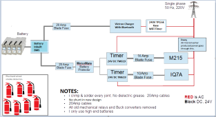
Updated Image from kundip:
.
View attachment 147287
 
You are already my hero, but f you can read the round trip resistance from battery positive connection wire all the way to positive MC4 connector disconnected from Microinverter and shorted to negative MC4 connector (also disconnected from Microinverter) and all the way back to battery negative connection wire connection in the way I outline, you will be even more so.
I measured three MicroInverters the best I could get was 0.1 ohms so I reckon 0.05 ohms on them all.
All circuit elements that can inturrept connection from battery to Microinverter including timer/relay and possibly also battery protector/relay will need to be closed (tricked into connecting the battery if they otherwise would disconnect it).
Did this no problem
The other thing you can do that would be helpful is to refine the simple wiring diagram you prepared. Every element in the paths needs to be shown. The blade fuse at the battery, the blade fuse at the Microinverter, the box which is the timer/relay, the box which is the battery protector (if the battery protector has inputs and outputs and can disconnect the battery, it also contains a relay).
This is the new circuit:
.
View attachment 147295
Circuit with relay:
.

It sounds as though you are attempting to adjust your booster while it is in the process of delivering power to the Microinverter and that is not going to work. The Microinverter is switching the voltage which causes the converter to change current which causes the Microinverter to change to different voltages, etc..,

A tiger chasing it’s take.
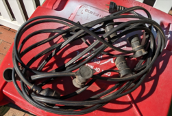
I am using old style globes (mix 25W to 100W) to get the draw through a 24V inverter pretty close to what I want.
Using an old party light(s) cord.
The draw is constant but the Boost Converter won't play ball.
I am probably barking up the wrong tree.
.
1682921200930.png 1682921613527.png
I’m guessing it’s pure blind luck that caused the one unit to lock on properly and begin generating power.
Definitely - I just will not touch it for fear of never getting it back.
If you want to try again, here is the sequence to use:

Decide upon voltage to use. The minimum voltage needs to be maximum battery voltage +2 volts and the maximum voltage to use should not be much much higher than the Vmp of your solar panels. Suggest you try 30VDC to start.
I used 30VDC.
I might have one more go at it.
Powering off of battery but not connected to Microinverter, you need to use a multimeter to measure output voltage and adjust pot until you hit your target voltage (30V).
I used my bench-top power supply - that is possibly an issue.
The next phase is easiest if your multimeter can measure DC current.

You need to calculate your target output power by taking the Microinverter output you are aiming for and deciding by Microinverter efficiency. For example:

250W / 95% = 263W.

Now divide by output voltage you set:

263W / 30VDC = 8.8A. That is the current setting you are aiming for.

So now you want to connect you multimeter to read current and adjust the current pot until you read 8.8A.

If you have a 100W power resistor handy, it’s a good idea to check output using that before connecting to your Microinverter.
OK I will try this out.
I was aiming for 150W @ 240VAC to try to assist others.
Connecting + and - across a 1 Ohm power resistor will put 8.8A across 1 Ohm for 8.8V of output (at 8.8A^2 x 1 Ohm = 77.4W of power). So if you put your multimeter in voltage mode and now read ~8.8V across the power resistor, you know the converter has been properly configured for 263W @ 30VDC.

You can now try connecting to your Microinverter but you need to make sure you have at least 0.05 Ohms of resistance between the booster and the Microinverter. If there is a timer relay in that path and is has over 0.5 ohms of resistance when closed/on, an additional power resistor may not be necessary, but if the timer controls DC power at the input of the booster and not the output, I’d advise you to add an 0.05 Ohm power resistor on the positive output of the booster before connecting to Microinverter.
OK I will need to read this a few times & try.
You cannot use a power resistor above 1.3 Ohm so let’s say you are using a 1Ohm power resistor.

You can also use 0 Ohms which is a short (no power resistor) but using a 1 Ohm power resistor would be better if you have one.

So now you are going to connect through your multimeter

I understand you are not worried about your Microinverters or ripple current and so that is why I am not suggesting you screw around with inductors.

My goal is to help you see whether you can successfully configure your DCDC boosters for use powering your mucroinverters without feeling they are unstable. First, you need to set the booster using a multimeter and not connected to a Microinverter as I have outlined above. And second, you need to add an 0.05 Ohm or 0.1 Ohm m 100W power resistor between booster output and Microinverter input to make it easier for your Microinverter to lock on to operating points.

For your use case (constant output level, simple ON / OFF control using timers and battery protectors) there is no advantage to using PWMs.

If a slightly more rigorous pot-setting methodology allows you to successfully use cheap DCDC boosters to power Microinverters and to stop feeling they are unstable or unreliable, I believe that is a more useful objective for you.
OK Thank you very much. - I will get better at this.
 
I measured three MicroInverters the best I could get was 0.1 ohms so I reckon 0.05 ohms on them all.

Did this no problem

This is the new circuit:
.
View attachment 147295
OK, so just to be clear you shorted Positive Microinverter input cable (MC4) to negative Microinverter cable (MC4) and read 0.1 Ohms for the farxsides of the cable that would connect to the battery, correct?

Do we can call it 0.05 - 0.149 ohms.

Just the amount of inline resistance agt is proving is needed to get the Enphase Microinverters to boot and lock-on correctly.
I am using old style globes (mix 25W to 100W) to get the draw through a 24V inverter pretty close to what I want.
So you are using the Microinverters to power lightbulbs to calibrate / set the DCDC converters when powering the Microinverter???

You need to configure the DCDC booster when it is not powering a Microinverter, then check the power you are getting from a microinverter in a second step. No touching the pots whole connected to a Microinverter.
Using an old party light(s) cord.
The draw is constant but the Boost Converter won't play ball.
I am probably barking up the wrong tree.
.
View attachment 147296 View attachment 147297

Definitely - I just will not touch it for fear of never getting it back.

I used 30VDC.
I might have one more go at it.
If you do, please don’t touch the one you have working.
I used my bench-top power supply - that is possibly an issue.
You mean you are powering the DCDC booster off of a DC power supply rather than a battery when you are adjusting the pots?

That should be OK as long as of the DC power supply is set to match battery voltage, current limit of the DC supply is well over fuse rating of the DCDC booster, and you are not powering a Microinverter when you are adjusting the posts.

Set the pots powering DC loads only and then check the power you are getting with a Microinverter (but no adjustments while connected to the Microinverter).
OK I will try this out.
I was aiming for 150W @ 240VAC to try to assist others.
If you want 150W out of the Microinverter, you will need 150W / 95% = 158W out of the DCDC booster.

158W = 30V x 5.27A.

If we assume there is 0.05 Ohms of resistance between DCDC booster and Microinverter, 5.27A will consume 5.27 x 5.27 x 0.05 = 1.4W in I^2R losses in the wires.

So aim for 159.4W = 5.3A @ 30 VDC.
OK I will need to read this a few times & try.

OK Thank you very much. - I will get better at this.
Setting the pot for maximum output voltage of the DCDC booster to 30VDC while powered by your benchtop DC supply and not connected to a Microinverter should be easy using a multimeter.

You turn either need to put your multimeter in DC current mode and adjust the current-controlling pot for 5.3A or connect positive and negative leads to a 1 ohm 100W power resistor and monitor voltage across the resistor using your multimeter while you trim the pot.

Voltage across a 1 ohm power resistor > 5.3V means current needs to be reduced.

Volrage across a - ohm power resistor < 5.3V means current needs to be increased.

When you’ve adjusted the current-controlling pot so your multimeter reads 5.3V across a 1 ohm power resistor, y I’ve got the correct trimmer for a maximum of 5.3A.

You can Joe connect the booster to a Microinverter (either power by battery or by your bench-top DC supply and use an AC current clamp to measure AC power output from the Microinverter (of your lightbulbs if you prefer ;)).

The key thing is yo make adjustments only with DC loads, not a Microinverter. The Microinverter is just a final check that your DC voltsge setting and DC current setting are delivering the power needed to get Microinverter output where you wanted it.

I realize this is a more painful trimming process than what you were using but I’m hoping you find it to be more successful and repeatable…
 
...Updated Image from kundip:
In post #64 you mentioned a BMS, but it was removed from the updated image, do you no longer use it - or perhaps it is an element of the battery system?

I also noticed you put the Envoy over the 240V line rather than off to the side as if current is going through it ... does that mean your Envoy is in an IQ Combiner box (with breakers) rather than a stand-alone Envoy?
 
Last edited:
In post #26 @newbostonconst says it works for him, he has a Victron Shunt. It's not his first rodeo, so the stuff between is probably: breakers, shunt, battery protector, BMS, relay, wire, and a bunch of crimps. Hopefully, they can confirm/deny.

In #46 @newbostonconst reports getting the DC Resistance light after reconfiguring his pack from 55 Ah to 550ah pack 20 cells 66 volts. No information on grounding.

Profiles?
Enphase's micros are controlled by their profiles, so possibly it's the profile causing the different behaviors. Although, @newbostonconst 's experience with just switching the batteries causing failures does point more towards internal resistance.
It would be interesting if those with Envoy's could tell us what profiles work for them.
@jimbob232 reports the UK profile, but if it's like here there's probably a dozen of them.
I had bought 120 cylindrical cells 55ah and I load tested them with a IQ7x and did it successfully like 7 times. Once I connected the IQ7x to the batteries connected to my hybrid inverter I got the grounding faults. I will try again and see if I can change the profiles in the IQ7x now that I got my Enphase installer degree.

I also did try putting a 1 to 1 toroidal isolation transformer on the AC side of the micro in an attempt to stop the ground path the IQ7x was faulting for. It still faulted.
 
In post #64 you mentioned a BMS, but it was removed from the updated image, do you no longer use it - or perhaps it is an element of the battery system?
Sorry - I get it it.
Each battery has its own BMS.
I have updated circuit.
I have not tested the IQ7A yet.
.
1682975207434.png

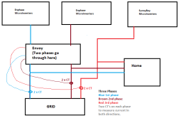
I also noticed you put the Envoy over the 240V line rather than off to the side as if current is going through it ... does that mean your Envoy is in an IQ Combiner box (with breakers) rather than a stand-alone Envoy?
Yes it is a combiner box with breakers.
The Envoy is across all three phases.
All Enphase MicroInverters go through two phases.
I measures all current going anywhere in the house going to grid or coming from grid.
I have a bout 10 Sunny Boy Micro Inverters going through the third phase.
.
1682976959487.png
 
The Envoy is across all three phases.
All Enphase MicroInverters go through two phases.
...I have a bout 10 Sunny Boy Micro Inverters going through the third phase.

Three phases? 3 wires going to the grid looks like three-phase, but sourced from devices as shown would be odd.

Three-phase power is rarely used in residences so suspect this might be something lost in translation. I've heard Australia is mostly single phase 230V @ 50 Hz. Possibly phase means "hot" wire or "circuit"?

A 240v microinverter here would have 3 wires, L1, L2, and ground. A three-phase microinverter here would have 4 wires: line 1, line 2, line 3, and ground, and I believe an Austrailian version would have to be the same.

If you're truly 3-phase power, please confirm.

Thanks for confirming the IQ Combiner box, seeing power flow through an Envoy as per the diagram definitely made me believe there was a missing component.
 
Back
Top