diy solar

diy solar

Using solar micro inverters with batteries instead of panels

V = L di/dt

8A/36e-6 seconds = 222,222 A/second

24V / (222,222 A/second) = 108 microhenry

[edit: 222,222 not 22,222 A/second]

"100mH inductors"

That's 1000x larger, seems like it would smooth it nicely.
I don't have the circuit or voltages.
You can download LTSpice for free, use to evaluate switching circuits.
SMPS are normally controlled to maintain voltage or current, and duty ratio adjusts as required.
In this case, you get whatever the motor speed control does.

What is the saturation current of the inductors?
 
Last edited:
V = L di/dt

8A/36e-6 seconds = 22,222 A/second

24V / (22,222 A/second) = 108 microhenry

"100mH inductors"
Thanks. So the 100uH inductors jimbob32 is experimenting with are much to
small to be smoothing the ripple current at the frequency and current range I am interested in.
That's 1000x larger, seems like it would smooth it nicely.

I don’t next see and what you mean by this? 100mH is 1000 times larger than what?

Ah, I get it now, 100mH is 1000 times larger than the 100uH inductors jimbob32 is experimenting with.

I see that 100mH represents an inductance of 15.7kOhms @ 25kHz, so all the higher-frequency harmonics when the PWM switches will see even higher impedance than that.

The 10,000uF input capacitance has an impedance of 637mOhm @ 25KHz, so it’s the inductor of hat will limit current flowing not the input through the entire 40uS period.

I don't have the circuit or voltages.
I don’t have the exact output circuit of these cheapo PWM controllers, but I think they can be modeled as an ideal current source (which in reality is a switched transistor which apparently gets hot if the high-frequency harmonics cannot be filtered out (according to jimbob32).

An 8S LiFePO4 battery source is being switched, so assume a range of 25.0-28.8V for the voltage being switched on and off by that ideal current source.

The Microinverter input capacitance is the 10,000uF 63V capacitor with a maximum ripple current requirement of 8A.

So if I understand the role on an online inductor correctly, it will represent a 15.7kOhm impedance to the primary
25KHz switching harmonic and will smooth out most of the high-frequency harmonics when the PWM switches on or off at 50% duty cycle or 10% duty cycle.

This means the current load on the transistor being switched @ 25Kh will be smoothed which should reduce heat induced by the switching events as jimbob32 has witnessed.

This also means that when switched ON, only a portion of the 40A gets through to charge the 10,000uF inout capacitor but when switched OFF, that same current continues through most of the OFF cycle so that the input capacitor continues charging throughout the entire 40uS period at a smoother more continuous current than 40A / 0A.

With a 50% duty cycle I can see that the charging current will be sinusoidal with an average current of 20A and ripple of a fraction of another +/-20A on top of that.

And I guess the same would largely be true at 10% duty cycle - average current of 4A and ripple of fraction of +/-20A on top of that.

Even if the 100mH inductor causes voltages to swing above the average voltage, they should never exceed the switched voltage of 25-28.8V and in any case, the 65V input capacitors should provide plenty of safety margin.

Looks like I’m going to have to pick up some 100mH inductors.
You can download LTSpice for free, use to evaluate switching circuits.
Too many projects on my plate right now and experimenting is both more direct and more fun (at the risk of killing components, PWM controllers, or even Microinverters :).

So I’ll save LTSpice to help me dive a mystery once I get a result I cannot understand, but thanks.
SMPS are normally controlled to maintain voltage or current, and duty ratio adjusts as required.
In this case, you get whatever the motor speed control does.
Do you believe that these DCDC boosters are essentially DC-powered SMPSes: https://www.amazon.com/AITRIP-Conve...+to+dc+boost+converter&qid=1682462580&sr=8-19
What is the saturation current of the inductors?
I have not purchased inductors yet so perhaps jmbob32 could answer that question (along with a link to his source for 100uH inductors :).

I just found these on AliExpress which are 3A 100mH inductors: https://m.aliexpress.us/item/225183...irect=y&gatewayAdapt=glo2usa&_randl_shipto=US

I assume that 3A limit is the saturation current?

Wire diameter is 0.5mm / 24AWG which is limited to 3.5A, so that is obviously going to be unsuitable for sustaining average currents of 20A let alone 4A…

Amazon has 20A inductors but only 100uH.

So it looks like some combination of a smaller inductor such as 300uH as jumbob32 has been experimenting to cut down on output transistor loading / heating with coupled an RC filter to reduce ripple-current reaching the input capacitors may be necessary…
 
V = L di/dt

8A/36e-6 seconds = 222,222 A/second

24V / (222,222 A/second) = 108 microhenry

[edit: 222,222 not 22,222 A/second]

"100mH inductors"
To see if I understand the computation correctly, I’m going to attempt to calculate my own inductor based on relaxed design specifications of 50% duty cycle and PWM ON current of 20A:

8A / 20e-6 seconds = 400,000A/second.
25V / 400,000A/second = 62.5 uH

So the reduced PWM current doesn’t really factor into it.

But why the 1000-fold increase from 62.5uH to 62.5mH?

For what we are trying do, limit current ripple from a PWM controller to 20-40% of raw ripple and hopefully also reduce heat generation from high-frequency current harmonics in the process, any inductor that can limit the swing around average current to +/-4A would suffice, even if it means peak voltage increasing by as much as +100%.

So a severely overdamped response that results in a ‘shark’s fin’ triangle wave would be fine, as long as the current excursions are limited to below +/-4A +/-25%.

Is that exactly what your 1000-fold increase in inductor size was achieving?
 
I wasn't recommending 1000-fold increase, just noting that the inductor size purchased by and mentioned in one post was 1000 times the size I estimated would have 8A ripple.

As voltage on capacitor changes, voltage across inductor changes and di/dt changes. But I avoid math involving waveforms and calculus as much as possible. I either calculate with DC applied or steady-state AC sine wave applied.

For a resistor, of course steady DC voltage means steady current.
RC circuit, exponential decay, so I either calculate peak current at beginning or RC time constant to reach 1/e of final voltage.
Inductor, steady voltage is steady ramp in current. Sine wave of some frequency sees reactive impedance, so RMS current from RMS voltage.
RL circuit, AC and DC impedance add orthogonally, and Pythagorean theorem gives hypotenuse, magnitude of impedance so current can be calculated. Trig gives phase angle.

LC has natural resonant frequency, and amplitude with forced sine wave is attenuated or boosted, to infinity at resonance. Resistance reduces and broadens the peak. For the PWM circuit, I figure it could be over/under/critically damped but I didn't try to analyze that.

I just tried, ignoring change in voltage across capacitor (assume infinite capacitance) to see what inductance would make current ripple the 8A you specified.

You mentioned frequency of switching. A square wave could be made up of sine wave fundamental and odd harmonics. Instead of trying to do that hairy math I just considered "on" time causing current ramp. "off" time was different.

Whether current drops to zero each cycle, pumps up to reach a steady state current with voltage ratio determined by switching duty ratio, or voltage rises above that ratio, depends on load and inductor value. This was part of SMPS theory class I took.

When switch is "off", in SMPS circuit the current circulates through a diode and keeps flowing into load as energy stored in inductor decays. I don't know if your PWM motor speed control has components which let that happen or just cause inductor's energy to dissipate. I was imagining the basic "buck" architecture.


With PWM connecting battery to capacitor, problem was the transistor was acting as a resistor between them and dissipating power as the voltages were brought to same value. Purpose of inductor is to let transistor switch as fast as possible, voltage drop across inductor instead. Power is then stored in inductor, later transferred to load. Similar to having square wave mechanical motion transferred to a load with spring instead of shock absorber.
 
I wasn't recommending 1000-fold increase, just noting that the inductor size purchased by and mentioned in one post was 1000 times the size I estimated would have 8A ripple.
Ah, that explains the confusion. I circled back and found the post where jimbob32 mentions he bought 100mH inductors but then goes on to say he experimented with 100uH inductors, so perhaps he can clarify whether the reference to 100mH was a typo or not.
As voltage on capacitor changes, voltage across inductor changes and di/dt changes. But I avoid math involving waveforms and calculus as much as possible. I either calculate with DC applied or steady-state AC sine wave applied.

For a resistor, of course steady DC voltage means steady current.
RC circuit, exponential decay, so I either calculate peak current at beginning or RC time constant to reach 1/e of final voltage.
Inductor, steady voltage is steady ramp in current. Sine wave of some frequency sees reactive impedance, so RMS current from RMS voltage.
Everything you state above summarizes my rudimentary level of understanding.
RL circuit, AC and DC impedance add orthogonally, and Pythagorean theorem gives hypotenuse, magnitude of impedance so current can be calculated. Trig gives phase angle.
Understand the concept but have never made use of the principle.
LC has natural resonant frequency, and amplitude with forced sine wave is attenuated or boosted, to infinity at resonance. Resistance reduces and broadens the peak. For the PWM circuit, I figure it could be over/under/critically damped but I didn't try to analyze that.
If we’re adding a 100uH inductor in series between a switched current source and an input capacitance, does that constitute LC?

I just tried, ignoring change in voltage across capacitor (assume infinite capacitance) to see what inductance would make current ripple the 8A you specified.
Ah, so I think you are saying the inductor feeding inout capacitance is LC and the minimum inductor needed to keep ripple under 8A is ~100uH. I’m not clearly understanding why the capacitance does not enter into the calculation but that’s OK.

The point is you’ve confirmed that addition of 300uH as jimbob32 has done has a good chance of keeping ripple current under 8A…
You mentioned frequency of switching. A square wave could be made up of sine wave fundamental and odd harmonics. Instead of trying to do that hairy math I just considered "on" time causing current ramp. "off" time was different.
I believe the PWM controllers have diode protection to prevent reverse current, so ‘OFF’ is probably more akin to output floating rather than grounded.
Whether current drops to zero each cycle, pumps up to reach a steady state current with voltage ratio determined by switching duty ratio, or voltage rises above that ratio, depends on load and inductor value. This was part of SMPS theory class I took.

When switch is "off", in SMPS circuit the current circulates through a diode and keeps flowing into load as energy stored in inductor decays. I don't know if your PWM motor speed control has components which let that happen or just cause inductor's energy to dissipate. I was imagining the basic "buck" architecture.
I’m not sure either but I think there are some schematics floating around on YouTube…

Just for my understanding, if a transistor is being used to drive current from a 25V battery through an inductor feeding a capacitor, what will happen in the two cases with and without a diode in series?

Inductor keeps pushing current into capacitor so capacitor voltage continues to rise.

Inductor is a decaying resistance so continued forward current means floating output voltage rises above 25VDC battery voltsge.

With a diode present, that output voltage will be able to whip up as far above 25V as needed and when the transistor is next turned on, current through the diode will quickly drive output voltage back to 25V.

Without a diode present, voltage rise on output of off transistor can reach the level the transistor can be damaged.

Is that about right?


With PWM connecting battery to capacitor, problem was the transistor was acting as a resistor between them and dissipating power as the voltages were brought to same value. Purpose of inductor is to let transistor switch as fast as possible, voltage drop across inductor instead. Power is then stored in inductor, later transferred to load. Similar to having square wave mechanical motion transferred to a load with spring instead of shock absorber.
Yes, all of this I understand.

100-300uH inductor allows transistor to switch quickly without driving much current and without generating much heat.

Input capacitance charging up more slowly with exponential input current rise for the full ON time (20uS for 25kHz square wave).

Output current to the Microinverter is average DC current, let’s say 10A for 250W of power, so input capacitance voltage is actually decreasing until input current through inductor increases to 10A, at which point it begins to increase.

Let’s assume inductor current increases to 14A or less by the end of ON time.

Inductor keeps supplying now-decaying level of current and as long as that current exceeds 10A, capacitor voltage will continue to rise (along with output voltage protected by diode).

Once inductor current drops below 10A, input capacitor voltage will begin to drop and output voltage along with it.

If we assume inductor current can drop to 0A before the end of OFF time, this will mean capacitor is discharging at 10A and is linearly decreasing both it’s voltage and the output voltage from whatever peak overshoot voltage it reached.

In the ideal scenario where the input capacitor discharged to exactly 25V just as inductor current decayed to 0A and transistor turns back on, this would mean both capacitor and output are both at 25V when transistor turns on, so no instantaneous current through the transistor when it is switched ON and about as efficient as possible.

In the more likely scenario where input capacitor has discharged to less than 25V (likely because of constant 10A discharge current), instantaneous step-up in output voltage (and inductor voltage) will be less than 25V which will ultimately translate to less-than-maximum 20A output current through the full cycle.

And in the most-likely scenario that current through inductor has decayed but not all the way to 0A, the inductor is essentially smoothing current through the OFF phase so that average current of 10A is being maintained with exponential increase to 14A or less during the ON phase and exponential decrease to 6A or more during the OFF phase.

So yes, since average current is irrelevant to the equation, we just need an inductor sized to maintain current below 50% of max ripple over a time which is 50% of overall period…

There is some reality-check needed in terms of max voltage swing of the input capacitor, but am I understanding thus correctly to the first-order?
 
I have not purchased inductors yet so perhaps jmbob32 could answer that question (along with a link to his source for 100uH inductors :).
Check this out! https://amzn.eu/d/3dHCsBG

These are what I'm using, 3 in series. Resistance is under 0.1 ohm but not zero so I think it can be considered as a LCR filter along with the input capacitors. They will take 15a but no idea what the saturation current is..
 
Check this out! https://amzn.eu/d/3dHCsBG

These are what I'm using, 3 in series. Resistance is under 0.1 ohm but not zero so I think it can be considered as a LCR filter along with the input capacitors. They will take 15a but no idea what the saturation current is..
100uH 15A. So your earlier reference to ‘1mH’ was a typo, I assume.

Do you have any way to measure AC current at 60Hz (50Hz in your case)?

The Microinverter should be switching between 2 operating points @ 60/50Hz and seeing the two voltages involved is pretty much impossible without a scope, but you might be able to at least measure the 50/60Hz AC current which would represent the ‘average’ DC current on top of which the 25kHz ripple current would ride…

22E4D279-C07A-454E-9757-D5BFC51BA6CD.png
 
It is an LC circuit. If the resonant frequency and under-damping allows, it may ring wildly. If a huge bulk capacitance, then my approximation of DC voltage applied to L alone might be OK.

If you use a transistor to pull an inductor up to +24VDC, current starts ramping up. When transistor turns off, inductor snaps to negative infinite volts. Or to the point of breaking down transistor. Parasitic capacitance (of inductor windings or circuit) may slow the rise (negative edge) time and limit voltage somewhat.

A reverse-biased diode across inductor while applying +24V will clip that negative infinity down to about -0.7V (not above +24V). Inductor will drive current through it for a while. That's the basic operation of a Buck regulator. A MOSFET in place of (or in parallel with) diode reduces dissipation and wasted power.

If what you have is a solenoid or relay you want to turn off fast, the freewheeling diode may keep current conducting too long. A resistor and diode in series is a snubber, and voltage is limited to I x R, can be sized to remain within transistor's voltage handling ability.

The orthogonal L R impedances might be useful for calculating current through transformer with secondary open, especially in saturation where inductive reactance is reduced. Conjugate impedance matching involves adding a "C" which resonates with "L" at operating frequency, so series LC presents zero ohm impedance. That leaves just "R", with lower impedance magnitude so higher current and power than what SQRT(R^2 + XL^2) let through.

At elevated frequencies, "skin effect" means resistive component of inductor is not same as DC resistance.

Bunch of EE stuff, some of which I occasionally apply. Mostly, I used Ohm's Law and Geometry.

"If we assume inductor current can drop to 0A before the end of OFF time"
That is "discontinuous conduction mode". If inductor is big enough for a given load, you get a DC current with sawtooth ripple riding on it. There are various SMPS modes of operation, producing various noise that may matter in sensitive applications.

I think you've got the first-order idea, which is about what I've got. I did go through the different switching regulator architectures in a college class. Someone who specializes in it would be more on top of the analysis. I've bounced around from microprocessor design to missiles to multi-chip modules to atomic mass spectrometers to vacuum applications involving electrons, and EMI/EMC. It keeps me confused and I have to dig up examples of how to do things.
 
I had some time last night to play around with the M250's; here's what I've discovered:
  • They will power up when connected directly to a battery, HOWEVER:
    • These models (and iq series) perform a DC resistance check at startup, and if too low they mark themselves offline (solid red LED) which persists across reboots. Per docs this can be rectified using an Envoy; I've ordered one from ebay. Scratch 2 m250's for now.
  • Inserting the 4 Ohm power resistor I use for precharging my off-grid AIO permitted the m250 to boot up and begin producing power. m250’s MPPT settled down to the minimum 16V supported by the m250, leaving a ~10.6V drop through the resistor at 10V/4R=2.5A=25W burned as heat, 2.5A*16V=40W output to AC. Not particularly efficient :)
  • Bypassing the resistor after MPPT stabilized didn't trigger the "DC Resistance Low" error. (yes risked 1 more for SCIENCE), but no power was produced - my ammeter suggests m250’s MPPT was repeatedly hunting and sleeping.
  • I tracked down a couple of 0.1 Ohm power resistors in my junk drawer.
    • Adding one to the DC input generated full power (9.5A, 248W AC, 10W heat loss on the 0.1 resistor) when 4W was removed
    • So I tried putting two in parallel (0.05 Ohm) which also worked, and as a bonus only generated 2.5W each.
    • Still probably need a heat sink for these and for the 4 Ohm bootstrap resistor.
My current thinking is that I'll use an 80A SSR to switch DC to the inverter(s), in parallel with a relay and in-line 4 Ohm resistor. The ardunio/esp32/rpi (haven't decided) would sequence the relay for bootup, then the SSR, then turn off the now-bypassed relay.

Before leaving this unattended I want to put snap-disc thermostats on at least the resistors/heat sink, maybe on the inverters as well. Those could either trigger the shunt trip relay in my main DC breaker (normally open), or could sit inline with the DC input to the inverter (normally closed).

After I have the full-power version stable, I'll add in another inverter via one of the cheap PWM units, maybe one with filtering and a third without.

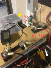
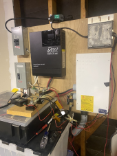
1682538511120.png1682538530811.png
 
Last edited:
I had some time last night to play around with the M250's; here's what I've discovered:
  • They will power up when connected directly to a battery, HOWEVER:
    • These models (and iq series) perform a DC resistance check at startup, and if too low they mark themselves offline (solid red LED) which persists across reboots. Per docs this can be rectified using an Envoy; I've ordered one from ebay. Scratch 2 m250's for now.
Interesting - Thanks for the discovery. I don’t know whether my NEP Microinverters perform a DC resistance check or not but I was thinking about connecting 50mOhm on Series and after your discovery, I’ll do at least that and use an old spare unit to boot the first time I try.
  • Inserting the 4 Ohm power resistor I use for precharging my inverter permitted it to boot up and begin producing power. MPPT pulls voltage all the way down to the minimum 16V supported by the m250, leaving a ~10V drop through the resistor at 10V/4R=2.5A=25W burned as heat, 2.5A*16V=40W output to AC. Not particularly efficient :)

Yes, 26VDC from the battery - 16VDC Vmppt_min means a maximum of 10VDC/4 Ohms = 2.5A into the inverter, so 2.5A x 16VDC = 40W of maximum output power.

  • Bypassing the resistor after MPPT stabilized didn't trigger the "DC Resistance Low" error. (yes risked 1 more for SCIENCE), but no power was produced - my ammeter suggests MPPT was repeatedly hunting and sleeping.
I wonder whether we can calculate the level of resistance it needs to lock-on.

Ref = Isc / (Voc - Vmp) = 1.093 Ohm for my 335W panels and 1.69 Ohms for my 380W panels, so I’d guess the resistance check can’t be looking for resistance of much more than an Ohm…
  • I tracked down a couple of 0.1 Ohm power resistors in my junk drawer.
    • Adding one to the DC input generated full power (9.5A, 248W AC, 10W heat loss on the resistor) when 4W was removed
    • So I tried putting two in parallel (0.05 Ohm) which also worked, and as a bonus only generates 2.5W on each.
    • Still probably need a heat sink for this and for the 4 Ohm bootstrap resistor.
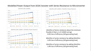
I decided from some crude modeling that I would put 50-100mOhm power resistors between my battery and my Microinverter to make it easier for the Microinverter MPPT to find a pair of suitable operating points and your experimental results perfectly confirm that theory:

Series Resistance.jpg
My current thinking is that I'll use an 80A SSR to switch DC to the inverter(s), in parallel with a relay and in-line 4 Ohm resistor.
The ardunio/esp32/rpi (haven't decided) would sequence the relay for bootup, then the SSR, then turn off the bypassed relay.
What is the contact resistance of your SSR? It alone might be able to replace your 50mOhm power resistor...

I want to thank you again for sharing this experiment - I've got some old inverters I might be prepared to sacrifice but this gives me an important heads-up for what to plan for. There is little difference between a 1-Ohm resistor and a 4-Ohm resistor for passing DC-resistance check in terms of cost or complexity, but since most solar panels seem to represent an effective resistance of ~1 Ohm past Vmp, I'm thinking that might be a safer resistance to use in case a specific microinverter also build in a 'resistance too high' fault mode.

But some way to pass the resistance check seems like an important safety check to avoid locking out microinverters.

You can of course progran your controller to control both switches, but an easier alternative would be to use a current switch on the AC output of the microinverter so that as soon as 40W is being generated (or 160W if you can pass the resistance check with a 1.0 Ohm resistor :)), the 50 mOhm resistor can be switched in. There is also no harm in leaving both resistors connected, so a simpler solution is to have a 1/4 Ohm resistance inline in parallel with a 50 mOhm switched resistance (or just an SSR in parallel if it represents enough resistance alone).

1 Ohm in parallel with 0.05 Ohms = 0.04762 Ohms so over 95% of current / power will be flowing through the SSR + power resistor branch and less than 5% of the current / power will be flowing through the unswitched 1 Ohm resistor (or even less if you stick with 4 Ohms).

So one AC relay/SSR to turn the microinverter ON and OFF and a second SSR controlled by a current switch once it detects that the microinverter has started generating power would be the Luddite's solution to this problem that some of the most active contributors to this thread such as kundip would prefer...


Before leaving this unattended I want to put snap-disc thermostats on at least the resistors/heat sink, maybe on the inverters as well. Those could either trigger the shunt relay in my main DC breaker (normally open), or could sit inline with the DC input to the inverter (normally closed).

After I have the full-power version stable, I'll add in another inverter via one of the cheap PWM units, maybe one with filtering and a third without.

View attachment 146647View attachment 146648
Nice. Are planning to test any cheap DCDC boosters as well?
 
It is an LC circuit. If the resonant frequency and under-damping allows, it may ring wildly. If a huge bulk capacitance, then my approximation of DC voltage applied to L alone might be OK.
In this case we are talking about an inductance of 0.3-1.0mH and a capacitance of 10-20mF - would a ratio of 10-67 qualify as 'huge'???
If you use a transistor to pull an inductor up to +24VDC, current starts ramping up. When transistor turns off, inductor snaps to negative infinite volts. Or to the point of breaking down transistor. Parasitic capacitance (of inductor windings or circuit) may slow the rise (negative edge) time and limit voltage somewhat.
This is the part I’m still struggling with. Current is flowing through inductor when transistor turns off. That same current continues to flow when transistor turns off, meaning voltage between output and input continues to increase.

If there is no reservoir of charge at the inductor input, I see how that could translate to negative infinite volts, but if there is any capacitance at the inductor input, voltage decrease will be much slower.

And if capacitance at inductor input equals capacitance at inductor output (what we’ve been calling the Input capacitance), the rate of voltage decrease at the inductor input will equal rate of continued voltage increase at the inductor output (both also dropping at a rate driven by average current output.

Of course, that added capacitance at the PWM output will bring back all of the high-harmonic heat that jimbob32 was originally motivated to avoid when he added the inductor in the first place, but since that added capacitor does not need to be the same size as the inout capacitance, it still offers an option to limit negative voltage swing during the OFF phase, right?
A reverse-biased diode across inductor while applying +24V will clip that negative infinity down to about -0.7V (not above +24V). Inductor will drive current through it for a while. That's the basic operation of a Buck regulator. A MOSFET in place of (or in parallel with) diode reduces dissipation and wasted power.
I understand that but feel like there should be a way to limit negative voltage swing so that it is at most done multiplier of positive voltage swing. From a starting voltage of 25V, the same computation you performed earlier means a ~100uH inductor will have a maximum of 8A flowing within the 20uS ON period. That should mean the maximum current that can be driving negative voltage swing at the beginning of OFF period is 8A + 10A = 18A.

18A for a full 20uS is 360uCoulomb which would drive a negative swing of only -36mV to 23.964V on a 10,000uF capacitor at inductor input.

If that added capacitance were dropped to only 100uF, wouldn’t that translate to worst-case negative voltage swing by the end of the OFF period to less than -3.6V to inductor input voltage that can’t be lower than 20.4V?

If what you have is a solenoid or relay you want to turn off fast, the freewheeling diode may keep current conducting too long. A resistor and diode in series is a snubber, and voltage is limited to I x R, can be sized to remain within transistor's voltage handling ability.
I don’t know protections a PWM may have to prevent negative voltage on the output, but I’d rather find a solution that keeps all voltages between 0-57.6VDC and does not need to rely on diodes or reverse-voltage protection.

The key epiphany I learned from you is that inductance translates to a maximum current change within an interval of time.

That means an inductor can limit current increase or decrease from a square wave and can maintain a known current swing around an average DC current.

I’m not going to bother with Spice yet, but I might try working op a piece wise-linear spreadsheet-based model such as the one I used to convince myself that 50-100mOhm between a battery and a Microinverter was needed to make the MPPT function more easily.

I’m going to try:

-Switched idealized current source (floating output when OFF)

-into smaller output capacitance

-into ~100uH inductor into 20,000uF input capacitance

-into idealized voltage source (MPPT).

I’ll report back when I have results to share.
The orthogonal L R impedances might be useful for calculating current through transformer with secondary open, especially in saturation where inductive reactance is reduced. Conjugate impedance matching involves adding a "C" which resonates with "L" at operating frequency, so series LC presents zero ohm impedance. That leaves just "R", with lower impedance magnitude so higher current and power than what SQRT(R^2 + XL^2) let through.

At elevated frequencies, "skin effect" means resistive component of inductor is not same as DC resistance.

Bunch of EE stuff, some of which I occasionally apply. Mostly, I used Ohm's Law and Geometry.
I appreciate all if this EE stuff but am hoping I can skate around it.

One question I do have for you, though:

If we’ve determined that a ~100uH inductor will protect a capacitor from seeing more than 8A of ripple current over a period of 20uS, doesn’t that mean that the same inductor would protect the same capacitance from the same >8A ripple current from a switched current source such as one of the cheap DCDC boosters (at least for current ripple at 25kHz or higher?

The inductor needs to be sized to handle the full DC current (8.3-10A) but since there is no ‘OFF’ period with a current source, when the Microinverter moves from Vmp to deliver target power @ programmed current (8.3A for 250W @ 30VDC) to much lower power and current at some voltage beyond prigramned maximum voltage of 30V, the inductor will act to limit both the rate f current increase as well as the rate of current decrease.

But since the timescale or inverters switching is 16.7ms (60Hz) versus the 40uS (25kHz) switching rate we’ve been talking about for PWM controllers, it should be a non-issue, shouldn’t it.

Can you see any reason an inductor should not be added inline between a DCDC booster and a Microinverter to protect the input caps of the Microinverter from high-frequency ripple current that might emit from the switched DCDC booster?
"If we assume inductor current can drop to 0A before the end of OFF time"
That is "discontinuous conduction mode". If inductor is big enough for a given load, you get a DC current with sawtooth ripple riding on it. There are various SMPS modes of operation, producing various noise that may matter in sensitive applications.
Noise does not matter in the case of a Microinverter being powered by a PWM controller, merely ripple current, so I think it is precisely that ‘DC current with sawtooth ripple riding on it’ that we are looking for.

Hopefully with your help I’m getting closer…
I think you've got the first-order idea, which is about what I've got. I did go through the different switching regulator architectures in a college class. Someone who specializes in it would be more on top of the analysis. I've bounced around from microprocessor design to missiles to multi-chip modules to atomic mass spectrometers to vacuum applications involving electrons, and EMI/EMC. It keeps me confused and I have to dig up examples of how to do things.
Your understanding goes leagues beyond mine and I appreciate your efforts to educate me. Between the evolving theory and the incoming experimental results, I’m increasingly confident this nut is on it’s way to being cracked…
 
Check this out! https://amzn.eu/d/3dHCsBG

These are what I'm using, 3 in series. Resistance is under 0.1 ohm but not zero so I think it can be considered as a LCR filter along with the input capacitors. They will take 15a but no idea what the saturation current is..
This is a 100uH inductor supposedly rated for 20A: https://www.amazon.com/gp/aw/d/B07F...&pd_rd_r=d1d32954-df3f-47f6-9cc4-f55a83238570

It’s using 0.8mm diameter / 20AWG wire which from everything I can find means maximum current is 11A (for chassis wiring).

So are inductors under DC current subject to different ampacity limits than what would apply to those same size wires carrying DC current in free air???
 
These 1.5mH inductors are rated for 20A but is using 1.8mm diameter / 13AWG wire with a chassis wiring ampacity of 35A: https://m.aliexpress.us/item/325680...irect=y&gatewayAdapt=glo2usa&_randl_shipto=US

Wouldn’t this be a better-suited inductor for the type of 20A PWM (+/-10A ripple on top of 10A DC) smoothing we are trying to achieve?
 
In this case we are talking about an inductance of 0.3-1.0mH and a capacitance of 10-20mF - would a ratio of 10-67 qualify as 'huge'???

1/(2 x pi x sqrt(0.001H x 0.01F)) = 50 Hz resonant frequency.

Way below switching speed of your speed control. But very close to ripple imposed by microinverter, so likely to build resonance unless damped. Have to evaluate impact of parasitic loss and source/load impedance.

This is the part I’m still struggling with. Current is flowing through inductor when transistor turns off. That same current continues to flow when transistor turns off, meaning voltage between output and input continues to increase.

Output voltage continues to rise.
Input was being pulled up to +24V (while it was pulling down, opposing the applied voltage).
When you stop pulling up, it snaps negative, gets clamped by diode if one is included.
Positive voltage increased current, negative voltage decreases it.

If there is no reservoir of charge at the inductor input, I see how that could translate to negative infinite volts, but if there is any capacitance at the inductor input, voltage decrease will be much slower.

Yes, interwinding capacitance and transistor drain capacitance reduce the voltage from negative infinity. But commonly enough inductive kick to kill devices.
We've blown a few bench supplies driving our magnetic components with DC.

And if capacitance at inductor input equals capacitance at inductor output (what we’ve been calling the Input capacitance), the rate of voltage decrease at the inductor input will equal rate of continued voltage increase at the inductor output (both also dropping at a rate driven by average current output.

Two identical capacitors in series is half the capacitance.

Of course, that added capacitance at the PWM output will bring back all of the high-harmonic heat that jimbob32 was originally motivated to avoid when he added the inductor in the first place, but since that added capacitor does not need to be the same size as the inout capacitance, it still offers an option to limit negative voltage swing during the OFF phase, right?

Would avoid adding capacitance on PWM output. In fact, often circuits (op-amp) driving large capacitive load do better with a series resistance. That helps their internal and external feedback achieve stability so they don't oscillate.

Snubbers are likely to be R, C, Diode in some combination. SMPS use FET for higher efficiency.

I understand that but feel like there should be a way to limit negative voltage swing so that it is at most done multiplier of positive voltage swing. From a starting voltage of 25V, the same computation you performed earlier means a ~100uH inductor will have a maximum of 8A flowing within the 20uS ON period. That should mean the maximum current that can be driving negative voltage swing at the beginning of OFF period is 8A + 10A = 18A.

Inductor can be pumped up to a much higher steady-state current than magnitude of ripple (depending on duty ratio and load). Smoother output but slower transient response.

18A for a full 20uS is 360uCoulomb which would drive a negative swing of only -36mV to 23.964V on a 10,000uF capacitor at inductor input.

If that added capacitance were dropped to only 100uF, wouldn’t that translate to worst-case negative voltage swing by the end of the OFF period to less than -3.6V to inductor input voltage that can’t be lower than 20.4V?

Probably. Capacitors reduce the voltage and the rate of rise. Ignition systems used capacitor across points so points could fully open without arcing, but still high enough di/dt to make high voltage on secondary.


I don’t know protections a PWM may have to prevent negative voltage on the output, but I’d rather find a solution that keeps all voltages between 0-57.6VDC and does not need to rely on diodes or reverse-voltage protection.

I would add external protection diode, sized according to inductor and driving conditions. I'm not sure a motor it was meant to drive would make as big a spike, so not sure what protection built in.

The key epiphany I learned from you is that inductance translates to a maximum current change within an interval of time.

For an applied voltage.
That's pretty much the definition of inductance.
(Start thinking about cores, saturation, hysteresis and things get messier but more real.)

That means an inductor can limit current increase or decrease from a square wave and can maintain a known current swing around an average DC current.

I’m not going to bother with Spice yet, but I might try working op a piece wise-linear spreadsheet-based model such as the one I used to convince myself that 50-100mOhm between a battery and a Microinverter was needed to make the MPPT function more easily.

Some math in Excel or Matlab is useful.
Programs that understand complex numbers are useful.

At half a dozen components, coding a passive filter circuit in Matlab got too messy for me.

Install LTSpice. Try an example filter circuit and an example SMPS IC circuit from their library.
Much easier to build off a copy of a running simulation.


I’m going to try:

-Switched idealized current source (floating output when OFF)

-into smaller output capacitance

-into ~100uH inductor into 20,000uF input capacitance

Look at its frequency response with and without resistance added.
Then try resistance over/under/equal to critically damped, look at time domain response to step function.

-into idealized voltage source (MPPT).

I’ll report back when I have results to share.

I appreciate all if this EE stuff but am hoping I can skate around it.

One question I do have for you, though:

If we’ve determined that a ~100uH inductor will protect a capacitor from seeing more than 8A of ripple current over a period of 20uS, doesn’t that mean that the same inductor would protect the same capacitance from the same >8A ripple current from a switched current source such as one of the cheap DCDC boosters (at least for current ripple at 25kHz or higher?

I think so. Within operating current range of inductor.
Unless you end up with a high Q tank circuit that amplifies voltage (that's how compact fluorescent starters work.)

The inductor needs to be sized to handle the full DC current (8.3-10A) but since there is no ‘OFF’ period with a current source, when the Microinverter moves from Vmp to deliver target power @ programmed current (8.3A for 250W @ 30VDC) to much lower power and current at some voltage beyond prigramned maximum voltage of 30V, the inductor will act to limit both the rate f current increase as well as the rate of current decrease.

But since the timescale or inverters switching is 16.7ms (60Hz) versus the 40uS (25kHz) switching rate we’ve been talking about for PWM controllers, it should be a non-issue, shouldn’t it.

A switching power supply control IC would adjust its PWM to regulate voltage as needed.
Your speed controller won't, might end up current limited (hope it has that feature) if constant duty ratio switching causes inductor circuit to run away. But no guarantees on output voltage. Except, I think for buck architecture it will stop at input voltage. Boost architecture goes higher than input (of course) and there may be no limit except something failing.

Can you see any reason an inductor should not be added inline between a DCDC booster and a Microinverter to protect the input caps of the Microinverter from high-frequency ripple current that might emit from the switched DCDC booster?

Noise does not matter in the case of a Microinverter being powered by a PWM controller, merely ripple current, so I think it is precisely that ‘DC current with sawtooth ripple riding on it’ that we are looking for.

Hopefully with your help I’m getting closer…

Your understanding goes leagues beyond mine and I appreciate your efforts to educate me. Between the evolving theory and the incoming experimental results, I’m increasingly confident this nut is on it’s way to being cracked…

Decades will do that to you. But mostly what I've learned being around it. I've dabbled in SMPS and seen a few things blow up, but haven't been full time on them. One thing I've seen is quality brands perform better. I tried an off-brand SMPS chip and while reference design worked, modified parameters for a different output never did. Better to stick with TI, LTC, Analog etc. and use design tools plus LTSpice. It was still an effort to model one unstable op-amp circuit. Output impedance varied with frequency according to the data sheet but not in model, so I had to add it externally so I could then simulate the fix.

Then I'm off to something different, so never an expert in the area.
 
So are inductors under DC current subject to different ampacity limits than what would apply to those same size wires carrying DC current in free air???

Typically rated at the current where inductance drop to 80% of what it was at low current.
The magnetic core gets toward saturation and becomes less effective.
Heat is an issue too, but likely heating of the core affecting inductance is limiting factor.
 
I used capacitor in series, inductor in parallel for impedance matching.
At elevated temperature performance of the circuit was poor.
When I touched the inductor and burned my finger I understood why.
After that I only did tuning (impedance matching) with capacitors, no inductors. I modifed the RF transformer I was driving so I could get away with that.
11 MHz, 700 Vpp into a capacitive load (part of an instrument.)
 
1/(2 x pi x sqrt(0.001H x 0.01F)) = 50 Hz resonant frequency.

Way below switching speed of your speed control. But very close to ripple imposed by microinverter, so likely to build resonance unless damped. Have to evaluate impact of parasitic loss and source/load impedance.
Too much more below for me to comment on now, but I did want to ask a follow-on question about this:

Does this mean that with a 100uH inductor rather than 1mH inductor we’d get a resonant frequency of 160Hz?

And if so, is that far enough away from 60Hz to avoid concerns associated with Microinverter ripple?

The 25kHz frequency is so fast I don’t believe it will be a factor other than the amount of 25kHz current ripple reaching the 10,000uF input capacitance of the Microinverter.

So any thoughts on what minimum resonant frequency avoids potential issues with 60Hz Microinverter ripple would be appreciated.

And also, in terms of damping the resonance, if I’m ready to add one or 2 50mOhm power resistors into the circuit to increase damping, where do you think they would be most effective?

Between the inductor output and the input capacitance?

Between the PWM output and the inductor input?

In parallel with the inductor?

Some combination of the above?
 
I decided from some crude modeling that I would put 50-100mOhm power resistors between my battery and my Microinverter to make it easier for the Microinverter MPPT to find a pair of suitable operating points and your experimental results perfectly confirm that theory:

Thanks for sharing your calculations - it's great to see model and reality line up so closely.!

What is the contact resistance of your SSR? It alone might be able to replace your 50mOhm power resistor...

Far too low, alas - I'm using the Thornwave 24v 80A ssr which consists of a driver and 6 parallel NTMFS5C604NL MOSFETs (60 V, 1.2 mW, 287 A). Measured voltage drop of 0.2mv at 10A == 0.2mOhm aligns pretty well with those chips' individual Rds(on) of 1.2mOhm.

So one AC relay/SSR to turn the microinverter ON and OFF and a second SSR controlled by a current switch once it detects that the microinverter has started generating power would be the Luddite's solution to this problem that some of the most active contributors to this thread such as kundip would prefer...

I'm a programmer by nature so I think in terms of state machines and such, but you're right hardware should be considered as well.

My next steps will be to clean up the installation, add a heat sink and thermal cutoff, and then let the inverter run for a week to confirm my assumption that DC resistance check only happens at startup. I'll also test whether the inverters are capable of extended operation at peak amps in normal solar panel usage that only happens for a few hours each day.
 
160 Hz sounds correct.
Away from the fundamental, but close to 180 Hz 3rd harmonic (which should be much lower amplitude than 60 Hz, much less to excite resonance.

To decide how much series or parallel resonance, you have to try an equation for Q (Q is voltage peak above stimulus signal, if I remember correctly.) Or SPICE. The driving and load impedances will also be a factor.
 
Thanks for sharing your calculations - it's great to see model and reality line up so closely.!

Far too low, alas - I'm using the Thornwave 24v 80A ssr which consists of a driver and 6 parallel NTMFS5C604NL MOSFETs (60 V, 1.2 mW, 287 A). Measured voltage drop of 0.2mv at 10A == 0.2mOhm aligns pretty well with those chips' individual Rds(on) of 1.2mOhm.
That’s a nice SSR! And yeah, you’ll need another ~50mOhms in series with that SSR.

But you don’t need a second switch on the 4 Ohm resistor - if you leave it permanently connected and only turn on the Microinverter begins outputting power, you’ll have ~0.07 Ohms in parallel with 4 ohms, meaning 68.8 mOhm parallel resistance. So 98.3% of the current will be running through the SSR + 0.05 Ohm resistor and only 4.3W will be flowing through the 4 Ohm resistor.

There is a tiny bit of added heat loss but it is not worth worrying about - assuming 10A total we’re talking 172mA through the 4 Ohm resistor for less than 120mW of wasted power…

By the way, I looked more closely at passing the resistance check with a 1 ohm resistor and you are lucky it passes with 4 Ohms for your Microinverters. 100W power resistors are easy to find but 200W power resistors, not so much and you’re right at the limit of 100W with 10A through a 1 Ohm resistor (and over that limit if your battery charges up past 26.0VDC)…

My Microinverters have a minimum MPPT voltage of 22V, so I only have 4VDC to worry about at 26V on the battery but as much as 6.8V if the battery is fully-charged to 28.8V. Even with a worst-case voltage of 6.8W, I’d only be looking at 46W through a 1 Ohm resistor…
I'm a programmer by nature so I think in terms of state machines and such, but you're right hardware should be considered as well.
A 1-4 Ohm permanent resistor with a typical SSR in parallel which gets turned on a current switch sensing AC output current is a nice simple solution to getting past the Resistance Check…
My next steps will be to clean up the installation, add a heat sink and thermal cutoff, and then let the inverter run for a week to confirm my assumption that DC resistance check only happens at startup.
Heatsink with thermal cutoff being added where, on the 0.5 Ohm power resistor?

The current switch solution has the added benefit that if there is a grid outage shutting down the system, it will automatically come back online once he grid is back up and the Resistance Check has passed…
I'll also test whether the inverters are capable of extended operation at peak amps in normal solar panel usage that only happens for a few hours each day.
Do you plan to use a fan or any other active cooling technique or passive only?
 
Back
Top