diy solar

diy solar

Using solar micro inverters with batteries instead of panels

I'm UK based, I do have an officially installed solar system that came with the house when I bought it. It's on an old/good generation tariff where there is a separate meter and I get paid on everything generated regardless if I use it or not. But it does mean I can't modify the system or tap off DC power.
Basically I want to do AC storage so I can reduce my bill and use everything I generate..

Arduino isn't really os based, it's much more like a plc but more codeable. And I'm probably going to do a hardware watchdog to shut everything down if the controller freezes...
Way to go.
Bye the bye.
I think no one can stop you putting up solar panels to charge batteries.
 
These PWM controllers also warn you about excess heat when running beyond 50% of max rating for a sustained period, but they are apparently starting from an efficiency of ~95% rather than 85%…

That’s 1/3rd the heat generation and it’s the reason the higher-powered DCSC-converters have much more serious heatsinks and even integrated fans compared to the PWM controllers.

I would be pretty upset if PWM had efficiency < 95%. It only needs a switching transistor and it probably has zero isolation (seeing as it operates at a single voltage) so overall is super simple.

DC DC converters need considerably more parts inside them -- blocking diodes, inductors, capacitors, etc. carrying significant levels of power.

Regarding the ripple discussion. There is a frequency component to this. Both in terms of the total current and the ripple current that a capacitor is rated to handle: https://www.vishay.com/docs/40057/ldacripp.pdf https://www.eevblog.com/forum/proje...-current-cap-that-isnt-physically-very-large/
From the handful of threads and spec sheets I looked at, for capacitors optimized for SMPS higher frequency is better. I don't know what kind of capacitor is in the microinverter.
 
I would be pretty upset if PWM had efficiency < 95%. It only needs a switching transistor and it probably has zero isolation (seeing as it operates at a single voltage) so overall is super simple.
I2R gets you coming and it gets you going. The YouTube videos where they characterize efficiency, I’m not sure they model the losses from whatever wiring they are using.
DC DC converters need considerably more parts inside them -- blocking diodes, inductors, capacitors, etc. carrying significant levels of power.

Regarding the ripple discussion. There is a frequency component to this. Both in terms of the total current and the ripple current that a capacitor is rated to handle: https://www.vishay.com/docs/40057/ldacripp.pdf https://www.eevblog.com/forum/proje...-current-cap-that-isnt-physically-very-large/
From the handful of threads and spec sheets I looked at, for capacitors optimized for SMPS higher frequency is better. I don't know what kind of capacitor is in the microinverter.
The input capacitors of a Microinverter only need to deal with 60/50Hz ripple, so to the extent capacitors able to handle higher-frequency ripple cost more, chances are the Microinverter input capacitors are more volnerable…

I’ve actually been doing some simple modeling of the magnitude of current ripple coming from 25KHz 40A PWM at 40% duty cycle feeding a Microinverter input and the results are surprising:

With only 20mOhms in between PWM output and Microinvetred inout, I get 435mA of current ripple @ 25KHz.

Adding a 10,000yF capacitance and another 20mOhm resistance does not reduce current ripple and actually increases it by 2.3% to 445mA.

Ditching the intermediate capacitor and just going to 40mA of resistance lowers the current ripple by 63% to 160mA.

And if I replace that 40mOhm resistor with a 100mOhm resistor I get a further 68% reduction in current ripple to only 51mA.

So despite the fact that adding a 100mOhm resistance between PWM and Microinverter will add ~2-3% of efficiency loss in terms of increased I2R, it looks like the best way to protect the input capacities of the Microinverter from high-frequency current ripple that might otherwise wear them out prematurely…

Interesting conclusion since that is not what I expected to see (thought the addition of an RC filter would have helped more…).
 
I recently picked up a bunch of used m250’s for ~$15 ea, am eager to test out some of the PWM ideas in this thread. They were cheap enough that I’m not too concerned about frying one or two or five in the process.

An m250 teardown video from a few years back shows 4 input caps which appear to be NCC KY-series . Those are billed as low ESR, long life, and high ripple tolerance - a happy surprise!
Welcome to the club.

I’m not sure which approach you are planning to use to get battery power into your m250s, but there a 3 different approaches being discussed here:

-direct connect - max current well in excess of any Iscmax spec is the risk but kundip has run for over two years now without issue. Current ripple and capacitor wear-out is not a concern with direct connect, merely the possibility of exceeding max current specs and whatever ill-effect that can have.

-through a DC-DC converter (most likely a booster) - current can be limited to stay under Iscmax spec, so that is no longer a concern but high-frequency current ripple may cause premature wearout of input capacitors. More on thought to prevent / limit that below. kundip has also run this configuration for over 2 years without issue.

-through a PWM motor speed controller - this will also be current-limited to whatever the max rating of the PWM controller can be but 20A exceeds most Iscmax specs, so we are assuming it is average current of 10A or less that matter rather than peak current. PWM is the worst-case for current ripple and jimbob32 originally suggested this approach and is likely to be our first member to test it. I’ve also got some PWM controllers on the way to test this approach later this year.

You have not said how much power you are looking to generate, but if it is enough to allow you to use 2-4 of your Microinverters and you are willing to contribute to our evolving experiment, it would be fantastic if you could test 2-4 different approaches in parallel as kundip has done to learn which approaches are most problematic (which could take years to see before a failure materializes.

I’m interested in both the DCDC booster and PWM controller approach since I want a way to control / throttle output and so I’ve started modeling current ripple and simulating various approaches to reducing it.

This recap is addressed to both jimbob32 and you in case it gives you any ideas you want to test with either a PWM controller or a DC-DC-booster:

-50% DUTY-CYCLE: the closer to 50% duty cycle you can be using a PWM controller, the more you can minimize current ripple. So 20A @ 50% duty-cycle is a better way to generate 250W of power from a 25V battery than 40A @ 25% duty-cycle.

-INLINE RESISTANCE: adding an 0.1 Ohm or 0.05 Ohm power resistor in between the output of the PWM controller or DC-DC-converter greatly reduced the current ripple reaching the input capacitors of the Microinverter. My crude simulations show at least a 75% reduction in current ripple when adding an 0.1 ohm resistor inline between DC output and Microinverter input versus only 0.01 Ohms of wiring resistance. Note that addition of an 0.1 ohm resistor inline with 250W of power from a 24VDC battery will come at a cost of ~4% lost efficiency because of increased I^2R losses.

-ADDED INPUT CAPACITANCE: my Microinverters have 10,800uF of input capacitors on each DC input, so I’ve also simulated the effect of adding another 10,000 uF of input capacitance and the result is a further reduction of current ripple by close to 50%. I don’t believe doubling input capacitance is likely to interfere with a Microinverter’s ability to respond @ 60Hz as needed, but that is tough to model and could potentially result in some lost efficiency.

So the addition of both an inline 0.1 Ohm resistor along with an added 10,000uF capacitor on the Microinverter input appears like it will reduce current ripple from a PWM or DCDC converter reaching the input capacitors of the Microinverter by close to 90%.

If you are planning to power your m250s through either PWM controllers or DC-DC converters, adding an 0.1 ohm resistor and 10,000uF capacitor to protect the Microinverter from current ripple seems like the safest way to do that and if you are willing to experiment, seeing how long an m250 without that protection lasts compared to one with it would be very interesting…
 
I recently picked up a bunch of used m250’s for ~$15 ea, am eager to test out some of the PWM ideas in this thread. They were cheap enough that I’m not too concerned about frying one or two or five in the process.

An m250 teardown video from a few years back shows 4 input caps which appear to be NCC KY-series . Those are billed as low ESR, long life, and high ripple tolerance - a happy surprise!
Interesting - thanks for the link. So we’ve got two reference points for Microinverter input caps:

Enphase M250: 4x3300uF = 13,200uF (60V)

NEP BDM300x2: 4x2700uF = 10,800uF (63V) (this is per each of 2 channels).

In the video, he states a 60V rating on the caps while the NCC KY-series you referenced seem to be rated to 100VDC.

I’m getting about the same level of ripple simulated with 0.05 ohm inline resistors as with 0.1ohm, so between the lower watt rating needed as well as the 50% reduction in efficiency loss and head generation, I just purchased a bunch of those (can always make a 0.1 Ohm resistor by putting two in series).

I’m shopping for 10,000 uF capacitors now and between wanting a high-quality / low ESR capacitor like the NCC KY capacitors you referenced or getting a lower-quality capacitor as a canary in the coal mine / sacrificial lamb, I’m torn. Perhaps I’ll get a few of both…
 
I recently picked up a bunch of used m250’s for ~$15 ea, am eager to test out some of the PWM ideas in this thread. They were cheap enough that I’m not too concerned about frying one or two or five in the process.
Great pickup!
An m250 teardown video from a few years back shows 4 input caps which appear to be NCC KY-series . Those are billed as low ESR, long life, and high ripple tolerance - a happy surprise!
Well worth buying. IMO
 
I recently picked up a bunch of used m250’s for ~$15 ea, am eager to test out some of the PWM ideas in this thread. They were cheap enough that I’m not too concerned about frying one or two or five in the process.

An m250 teardown video from a few years back shows 4 input caps which appear to be NCC KY-series . Those are billed as low ESR, long life, and high ripple tolerance - a happy surprise!
By the way, if you know anything about capacitor specs and where to purchase capacitors with known ESR or current ripple specs, any recommendations would be appreciated.

These 10,000uF capacitors on Amazon are not to expensive, but no way to know how they measure up on ESR or tolerance to current ripple: https://www.amazon.com/Jadeshay-Amp...52-9e7e-7d53b298a746&pd_rd_i=B07R1X6DPJ&psc=1

Those higher-quality NCC-KY capacitors you referenced represent 10s of millohms at 100Kz and can handle ripple currents of multiple amps @ 100KHz, for example, but buying capacitors seems like much more of the Wild West than buying power resistors, so any advice would be appreciated.
 
I recently picked up a bunch of used m250’s for ~$15 ea, am eager to test out some of the PWM ideas in this thread. They were cheap enough that I’m not too concerned about frying one or two or five in the process.

An m250 teardown video from a few years back shows 4 input caps which appear to be NCC KY-series . Those are billed as low ESR, long life, and high ripple tolerance - a happy surprise!
You seem to know a thing or two about capacitors, so I’m hoping you might have some insights to share.

I managed to track down the specs on the output capacitors of my DC-DC boosters and bracket the specs of the inout capacitors of my NEP BDM300x2 Dual-Microinverters:

DCDC booster 3 x 470uF Chengxing KM
1000-2000 hour lifetime
918mA ripple current (3 x 918mA = 2.754A)
3 x 470uF = 1410uF total

BDM300x2 4 x 2700uF Samxon GY
4000-10,000 hour lifetime
>1.39A ripple (4 x 1.39 = >5.56A / input)
4 x 2700uF = 10,800uF total

So it’s blindingly clear to me that the low-quality capacitors on the DC-DC converters will give up the ghost long before the input caps on the microinverters, but I’d like to attempt to extend their lifetime by adding another ~2000-5000uF of capacitance on the output.

Any of the cheap capacitors I can find on Amazon are likely to be similar in specs to the poor caps on the DC-DC converter but should at least extend their lifetime.

And as I contemplate more what it would mean to use a PWM, I’m understanding more clearly that while it’s straightforward to protect the Microinverter input capacitors by adding a capacitor to the DC input, finding a budget capacitor that can withstand 20A of ripple current from a PWM @ 25kHz looks to be a challenge (or at least expensive).

So I’ll focus on using the DC-DC boosters I’ve purchased and let you and jimbob32 take the lead on the PWM approach to powering Microinverters with stored battery energy…
 
( Thanks @fafrd for the expansive summary above! I'm tied up with work/etc for a few days but will report back. Capsule version of my goals: I've got 6kw of AC coupled solar via enphase iq7; 7kwh of storage charged by an SRNE 3kw 24v AIO; hoping to set up 1-1.5KW of m250's to dynamically load shift from earlier in the day to 4-9pm.)

Any of the cheap capacitors I can find on Amazon are likely to be similar in specs to the poor caps on the DC-DC converter but should at least extend their lifetime.

You might take a look at Digikey, Mouser, or one of the other well-known component distributors as alternatives to Amazon. They all offer parametric search e.g. "show me in-stock 3300uF radial electrolytics with X ripple current capability", shipping from either is quick and pretty inexpensive, and much higher confidence you're getting genuine and not counterfeit parts.

I believe the caps from the m250 video are these: https://www.mouser.com/ProductDetail/United-Chemi-Con/EKY-500ELL332MM40S
 
Last edited:
You seem to know a thing or two about capacitors, so I’m hoping you might have some insights to share.

I managed to track down the specs on the output capacitors of my DC-DC boosters and bracket the specs of the inout capacitors of my NEP BDM300x2 Dual-Microinverters:

DCDC booster 3 x 470uF Chengxing KM
1000-2000 hour lifetime
918mA ripple current (3 x 918mA = 2.754A)
3 x 470uF = 1410uF total

BDM300x2 4 x 2700uF Samxon GY
4000-10,000 hour lifetime
>1.39A ripple (4 x 1.39 = >5.56A / input)
4 x 2700uF = 10,800uF total

So it’s blindingly clear to me that the low-quality capacitors on the DC-DC converters will give up the ghost long before the input caps on the microinverters, but I’d like to attempt to extend their lifetime by adding another ~2000-5000uF of capacitance on the output.

Any of the cheap capacitors I can find on Amazon are likely to be similar in specs to the poor caps on the DC-DC converter but should at least extend their lifetime.

And as I contemplate more what it would mean to use a PWM, I’m understanding more clearly that while it’s straightforward to protect the Microinverter input capacitors by adding a capacitor to the DC input, finding a budget capacitor that can withstand 20A of ripple current from a PWM @ 25kHz looks to be a challenge (or at least expensive).

So I’ll focus on using the DC-DC boosters I’ve purchased and let you and jimbob32 take the lead on the PWM approach to powering Microinverters with stored battery energy…
Unfortunately UK electricity meters don't work exactly like that... they use an energy 'bucket' that contains 3600J (one Watt-hour), every time you empty it by using the energy it increments the counter for billing, so you need to be accurate and fast.

I also have a device to divert excess AC power to my immersion heater, this has to use individual ac wave control to cope with the above - e.g for a 3kw heater you want to run at 5% (150w) it activates 1 in 20 full ac waves.....the solar then replenishes the 'bucket' before the heater fires again so you don't increment the billing counter.

I think i'm just going to try the PWM controller and see how long it lasts, and maybe an inductor on the output before the inverter as well.

Failing that, i may also try plan B, with a DC SSR switched at about 500-1000Hz but they're about £50 so i don't want to do that just yet...


OK. Was worth a shot.
FYI 200W Micro Inverter:
Not something I can do:
 
So the addition of both an inline 0.1 Ohm resistor along with an added 10,000uF capacitor on the Microinverter input appears like it will reduce current ripple from a PWM or DCDC converter reaching the input capacitors of the Microinverter by close to 90%.

If you are planning to power your m250s through either PWM controllers or DC-DC converters, adding an 0.1 ohm resistor and 10,000uF capacitor to protect the Microinverter from current ripple seems like the safest way to do that and if you are willing to experiment, seeing how long an m250 without that protection lasts compared to one with it would be very interesting…
Thanks for this recap, it is very interesting to me.

I have just received some 100mH inductors and I am intending to try a LC filter on the pwm output, handily these have 0.1 ohm resistance as well which looks like it will be beneficial.

One thing I did notice is that the pwm duty to put 4a into the inverter was very low (just based on knob position) which hints at high instantaneous current to hit the average 4a. I think this will be a good clue to see if the filter improves things, and probably why the pwm unit was heating up quickly...
 
Well i've given it a try with some inductors.

1 made little difference, 2 was noticeably better then...

With 3 Dollatek 100uH inductors in series on the PWM output then feeding into the M250, the PWM board no longer gets hot, barely above room temperature running ~3A for a few minutes. I think this confirms that switching the current into the M250 is higher than you think unless there's something calming it down - the measured current on my PSU and the power output is an average but the peak is based on charging the capacitors and the impedance of the supply/wiring.
I did a quick and probably very inaccurate circuit sim and it did show that inductance in series is very helpful in reducing the switching currents down.

The PWM control knob still controls output power _reasonably_ well , but there's now another effect going on where i think the inverter is now trying to control the voltage/power input level and it's hunting a bit - by maybe 0.5A as measured on the PSU. I am now wondering if additional capacitance will help this or possibly a power resistor across the pwm unit...it just needs something to change the characteristics of the system a bit to stop it hunting.
 

Attachments

  • Inductors added.PNG
    Inductors added.PNG
    346.9 KB · Views: 4
Transistors switching inductor rather than capacitor lets the voltage drop be across inductor, so you've got something more like switching power supply.

When transistor turns off, current in inductor makes voltage fly to opposite polarity, which can blow up transistors. consider a snubber, clamping diode, etc.

It is very common for switching of inductive loads to kill transistors and burn relays.
 
Thanks for this recap, it is very interesting to me.

I have just received some 100mH inductors and I am intending to try a LC filter on the pwm output, handily these have 0.1 ohm resistance as well which looks like it will be beneficial.

One thing I did notice is that the pwm duty to put 4a into the inverter was very low (just based on knob position) which hints at high instantaneous current to hit the average 4a. I think this will be a good clue to see if the filter improves things, and probably why the pwm unit was heating up quickly...
Will be interested to learn what you discover…
 
Transistors switching inductor rather than capacitor lets the voltage drop be across inductor, so you've got something more like switching power supply.

When transistor turns off, current in inductor makes voltage fly to opposite polarity, which can blow up transistors. consider a snubber, clamping diode, etc.

It is very common for switching of inductive loads to kill transistors and burn relays.
I'm hoping the pwm unit will be ok with the inductors as it is designed to drive motors...
 
Oh, I was thinking PWM charger.
Yes, probably has reverse polarity protection diodes on its transistors.
But it never expected to drive a capacitive load. With PWM (part of a switcher), most of the power dissipation in transistor is during the voltage transitions, which takes a long time charging capacitor. Your inductor should do a lot to help that.
It certainly helps, without the inductors the switching transistor got very hot, it now doesn't.
 
I'm hoping the pwm unit will be ok with the inductors as it is designed to drive motors...
I can't recall whether dynamic control of battery-driven power is a priority to you or not, but as you add inductors it occurs to that you might want to get ahold of one of these: https://www.amazon.com/AITRIP-Conve...8TWKK5Z9/ref=psdc_10967761_t3_B0756HQTRM?th=1

I picked up 3 of these from AliExpress for less than half the price of each these 2 from Amazon, so once you start adding up the cost of inductors, PWM, etc... this quickly becomes a cost-effective fully-integrated solution.

8A max without added cooling = 200W max input power from a 25VDC battery translating to 160-180W max output assuming efficiency of 80-90%. By adding a fan, you should be able deliver 250W (or you can use 2 units in parallel).

You will need to boost by at least 2 volts so if your battery varies between 28.8V when fully-charged to 25V when fully discharged, you'll need to configure output voltage for 29.0V and then set the output current to 5.5-6.2A (depending on measured efficiency).

Current ripple and stability of output are the two criticisms that have been levelled against these cheapo DCDC boosters but since these are precisely the areas you are looking at and characterizing, could make sense to include one of these in the mix as a reference...
 
Oh, I was thinking PWM charger.
Yes, probably has reverse polarity protection diodes on its transistors.
But it never expected to drive a capacitive load. With PWM (part of a switcher), most of the power dissipation in transistor is during the voltage transitions, which takes a long time charging capacitor. Your inductor should do a lot to help that.
Here are some parameters I'll throw out at you in case you have a suggestion for size of inductor that could help:

PWM current: 40A
Duty Cycle: 10% @ 25kHz (4us ON, 36us OFF)
Input Capacitance being powered: 10,000uF
Maximum Ripple Current at Input: 8A
 
V = L di/dt

8A/36e-6 seconds = 222,222 A/second

24V / (222,222 A/second) = 108 microhenry

[edit: 222,222 not 22,222 A/second]

"100mH inductors"

That's 1000x larger, seems like it would smooth it nicely.
I don't have the circuit or voltages.
You can download LTSpice for free, use to evaluate switching circuits.
SMPS are normally controlled to maintain voltage or current, and duty ratio adjusts as required.
In this case, you get whatever the motor speed control does.

What is the saturation current of the inductors?
 
Last edited:
V = L di/dt

8A/36e-6 seconds = 22,222 A/second

24V / (22,222 A/second) = 108 microhenry

"100mH inductors"
Thanks. So the 100uH inductors jimbob32 is experimenting with are much to
small to be smoothing the ripple current at the frequency and current range I am interested in.
That's 1000x larger, seems like it would smooth it nicely.

I don’t next see and what you mean by this? 100mH is 1000 times larger than what?

Ah, I get it now, 100mH is 1000 times larger than the 100uH inductors jimbob32 is experimenting with.

I see that 100mH represents an inductance of 15.7kOhms @ 25kHz, so all the higher-frequency harmonics when the PWM switches will see even higher impedance than that.

The 10,000uF input capacitance has an impedance of 637mOhm @ 25KHz, so it’s the inductor of hat will limit current flowing not the input through the entire 40uS period.

I don't have the circuit or voltages.
I don’t have the exact output circuit of these cheapo PWM controllers, but I think they can be modeled as an ideal current source (which in reality is a switched transistor which apparently gets hot if the high-frequency harmonics cannot be filtered out (according to jimbob32).

An 8S LiFePO4 battery source is being switched, so assume a range of 25.0-28.8V for the voltage being switched on and off by that ideal current source.

The Microinverter input capacitance is the 10,000uF 63V capacitor with a maximum ripple current requirement of 8A.

So if I understand the role on an online inductor correctly, it will represent a 15.7kOhm impedance to the primary
25KHz switching harmonic and will smooth out most of the high-frequency harmonics when the PWM switches on or off at 50% duty cycle or 10% duty cycle.

This means the current load on the transistor being switched @ 25Kh will be smoothed which should reduce heat induced by the switching events as jimbob32 has witnessed.

This also means that when switched ON, only a portion of the 40A gets through to charge the 10,000uF inout capacitor but when switched OFF, that same current continues through most of the OFF cycle so that the input capacitor continues charging throughout the entire 40uS period at a smoother more continuous current than 40A / 0A.

With a 50% duty cycle I can see that the charging current will be sinusoidal with an average current of 20A and ripple of a fraction of another +/-20A on top of that.

And I guess the same would largely be true at 10% duty cycle - average current of 4A and ripple of fraction of +/-20A on top of that.

Even if the 100mH inductor causes voltages to swing above the average voltage, they should never exceed the switched voltage of 25-28.8V and in any case, the 65V input capacitors should provide plenty of safety margin.

Looks like I’m going to have to pick up some 100mH inductors.
You can download LTSpice for free, use to evaluate switching circuits.
Too many projects on my plate right now and experimenting is both more direct and more fun (at the risk of killing components, PWM controllers, or even Microinverters :).

So I’ll save LTSpice to help me dive a mystery once I get a result I cannot understand, but thanks.
SMPS are normally controlled to maintain voltage or current, and duty ratio adjusts as required.
In this case, you get whatever the motor speed control does.
Do you believe that these DCDC boosters are essentially DC-powered SMPSes: https://www.amazon.com/AITRIP-Conve...+to+dc+boost+converter&qid=1682462580&sr=8-19
What is the saturation current of the inductors?
I have not purchased inductors yet so perhaps jmbob32 could answer that question (along with a link to his source for 100uH inductors :).

I just found these on AliExpress which are 3A 100mH inductors: https://m.aliexpress.us/item/225183...irect=y&gatewayAdapt=glo2usa&_randl_shipto=US

I assume that 3A limit is the saturation current?

Wire diameter is 0.5mm / 24AWG which is limited to 3.5A, so that is obviously going to be unsuitable for sustaining average currents of 20A let alone 4A…

Amazon has 20A inductors but only 100uH.

So it looks like some combination of a smaller inductor such as 300uH as jumbob32 has been experimenting to cut down on output transistor loading / heating with coupled an RC filter to reduce ripple-current reaching the input capacitors may be necessary…
 
V = L di/dt

8A/36e-6 seconds = 222,222 A/second

24V / (222,222 A/second) = 108 microhenry

[edit: 222,222 not 22,222 A/second]

"100mH inductors"
To see if I understand the computation correctly, I’m going to attempt to calculate my own inductor based on relaxed design specifications of 50% duty cycle and PWM ON current of 20A:

8A / 20e-6 seconds = 400,000A/second.
25V / 400,000A/second = 62.5 uH

So the reduced PWM current doesn’t really factor into it.

But why the 1000-fold increase from 62.5uH to 62.5mH?

For what we are trying do, limit current ripple from a PWM controller to 20-40% of raw ripple and hopefully also reduce heat generation from high-frequency current harmonics in the process, any inductor that can limit the swing around average current to +/-4A would suffice, even if it means peak voltage increasing by as much as +100%.

So a severely overdamped response that results in a ‘shark’s fin’ triangle wave would be fine, as long as the current excursions are limited to below +/-4A +/-25%.

Is that exactly what your 1000-fold increase in inductor size was achieving?
 
I wasn't recommending 1000-fold increase, just noting that the inductor size purchased by and mentioned in one post was 1000 times the size I estimated would have 8A ripple.

As voltage on capacitor changes, voltage across inductor changes and di/dt changes. But I avoid math involving waveforms and calculus as much as possible. I either calculate with DC applied or steady-state AC sine wave applied.

For a resistor, of course steady DC voltage means steady current.
RC circuit, exponential decay, so I either calculate peak current at beginning or RC time constant to reach 1/e of final voltage.
Inductor, steady voltage is steady ramp in current. Sine wave of some frequency sees reactive impedance, so RMS current from RMS voltage.
RL circuit, AC and DC impedance add orthogonally, and Pythagorean theorem gives hypotenuse, magnitude of impedance so current can be calculated. Trig gives phase angle.

LC has natural resonant frequency, and amplitude with forced sine wave is attenuated or boosted, to infinity at resonance. Resistance reduces and broadens the peak. For the PWM circuit, I figure it could be over/under/critically damped but I didn't try to analyze that.

I just tried, ignoring change in voltage across capacitor (assume infinite capacitance) to see what inductance would make current ripple the 8A you specified.

You mentioned frequency of switching. A square wave could be made up of sine wave fundamental and odd harmonics. Instead of trying to do that hairy math I just considered "on" time causing current ramp. "off" time was different.

Whether current drops to zero each cycle, pumps up to reach a steady state current with voltage ratio determined by switching duty ratio, or voltage rises above that ratio, depends on load and inductor value. This was part of SMPS theory class I took.

When switch is "off", in SMPS circuit the current circulates through a diode and keeps flowing into load as energy stored in inductor decays. I don't know if your PWM motor speed control has components which let that happen or just cause inductor's energy to dissipate. I was imagining the basic "buck" architecture.


With PWM connecting battery to capacitor, problem was the transistor was acting as a resistor between them and dissipating power as the voltages were brought to same value. Purpose of inductor is to let transistor switch as fast as possible, voltage drop across inductor instead. Power is then stored in inductor, later transferred to load. Similar to having square wave mechanical motion transferred to a load with spring instead of shock absorber.
 
I wasn't recommending 1000-fold increase, just noting that the inductor size purchased by and mentioned in one post was 1000 times the size I estimated would have 8A ripple.
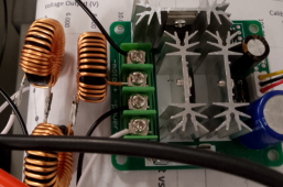
Ah, that explains the confusion. I circled back and found the post where jimbob32 mentions he bought 100mH inductors but then goes on to say he experimented with 100uH inductors, so perhaps he can clarify whether the reference to 100mH was a typo or not.
As voltage on capacitor changes, voltage across inductor changes and di/dt changes. But I avoid math involving waveforms and calculus as much as possible. I either calculate with DC applied or steady-state AC sine wave applied.

For a resistor, of course steady DC voltage means steady current.
RC circuit, exponential decay, so I either calculate peak current at beginning or RC time constant to reach 1/e of final voltage.
Inductor, steady voltage is steady ramp in current. Sine wave of some frequency sees reactive impedance, so RMS current from RMS voltage.
Everything you state above summarizes my rudimentary level of understanding.
RL circuit, AC and DC impedance add orthogonally, and Pythagorean theorem gives hypotenuse, magnitude of impedance so current can be calculated. Trig gives phase angle.
Understand the concept but have never made use of the principle.
LC has natural resonant frequency, and amplitude with forced sine wave is attenuated or boosted, to infinity at resonance. Resistance reduces and broadens the peak. For the PWM circuit, I figure it could be over/under/critically damped but I didn't try to analyze that.
If we’re adding a 100uH inductor in series between a switched current source and an input capacitance, does that constitute LC?

I just tried, ignoring change in voltage across capacitor (assume infinite capacitance) to see what inductance would make current ripple the 8A you specified.
Ah, so I think you are saying the inductor feeding inout capacitance is LC and the minimum inductor needed to keep ripple under 8A is ~100uH. I’m not clearly understanding why the capacitance does not enter into the calculation but that’s OK.

The point is you’ve confirmed that addition of 300uH as jimbob32 has done has a good chance of keeping ripple current under 8A…
You mentioned frequency of switching. A square wave could be made up of sine wave fundamental and odd harmonics. Instead of trying to do that hairy math I just considered "on" time causing current ramp. "off" time was different.
I believe the PWM controllers have diode protection to prevent reverse current, so ‘OFF’ is probably more akin to output floating rather than grounded.
Whether current drops to zero each cycle, pumps up to reach a steady state current with voltage ratio determined by switching duty ratio, or voltage rises above that ratio, depends on load and inductor value. This was part of SMPS theory class I took.

When switch is "off", in SMPS circuit the current circulates through a diode and keeps flowing into load as energy stored in inductor decays. I don't know if your PWM motor speed control has components which let that happen or just cause inductor's energy to dissipate. I was imagining the basic "buck" architecture.
I’m not sure either but I think there are some schematics floating around on YouTube…

Just for my understanding, if a transistor is being used to drive current from a 25V battery through an inductor feeding a capacitor, what will happen in the two cases with and without a diode in series?

Inductor keeps pushing current into capacitor so capacitor voltage continues to rise.

Inductor is a decaying resistance so continued forward current means floating output voltage rises above 25VDC battery voltsge.

With a diode present, that output voltage will be able to whip up as far above 25V as needed and when the transistor is next turned on, current through the diode will quickly drive output voltage back to 25V.

Without a diode present, voltage rise on output of off transistor can reach the level the transistor can be damaged.

Is that about right?


With PWM connecting battery to capacitor, problem was the transistor was acting as a resistor between them and dissipating power as the voltages were brought to same value. Purpose of inductor is to let transistor switch as fast as possible, voltage drop across inductor instead. Power is then stored in inductor, later transferred to load. Similar to having square wave mechanical motion transferred to a load with spring instead of shock absorber.
Yes, all of this I understand.

100-300uH inductor allows transistor to switch quickly without driving much current and without generating much heat.

Input capacitance charging up more slowly with exponential input current rise for the full ON time (20uS for 25kHz square wave).

Output current to the Microinverter is average DC current, let’s say 10A for 250W of power, so input capacitance voltage is actually decreasing until input current through inductor increases to 10A, at which point it begins to increase.

Let’s assume inductor current increases to 14A or less by the end of ON time.

Inductor keeps supplying now-decaying level of current and as long as that current exceeds 10A, capacitor voltage will continue to rise (along with output voltage protected by diode).

Once inductor current drops below 10A, input capacitor voltage will begin to drop and output voltage along with it.

If we assume inductor current can drop to 0A before the end of OFF time, this will mean capacitor is discharging at 10A and is linearly decreasing both it’s voltage and the output voltage from whatever peak overshoot voltage it reached.

In the ideal scenario where the input capacitor discharged to exactly 25V just as inductor current decayed to 0A and transistor turns back on, this would mean both capacitor and output are both at 25V when transistor turns on, so no instantaneous current through the transistor when it is switched ON and about as efficient as possible.

In the more likely scenario where input capacitor has discharged to less than 25V (likely because of constant 10A discharge current), instantaneous step-up in output voltage (and inductor voltage) will be less than 25V which will ultimately translate to less-than-maximum 20A output current through the full cycle.

And in the most-likely scenario that current through inductor has decayed but not all the way to 0A, the inductor is essentially smoothing current through the OFF phase so that average current of 10A is being maintained with exponential increase to 14A or less during the ON phase and exponential decrease to 6A or more during the OFF phase.

So yes, since average current is irrelevant to the equation, we just need an inductor sized to maintain current below 50% of max ripple over a time which is 50% of overall period…

There is some reality-check needed in terms of max voltage swing of the input capacitor, but am I understanding thus correctly to the first-order?
 

diy solar

diy solar
Back
Top