diy solar

diy solar

Using solar micro inverters with batteries instead of panels

Thanks for the detailed reply. I’d thought you were switching AC so I’m glad I asked you for a clarification.

I assume you have a multimeter so if you’d like to put on a bit off effort to address the concerns being raised about precharge, perhaps you could measure the DC voltage on the output of the relay in the morning before it turns on.
I have measured 4 MicroInverters here are the voltages:
0.014
0.022
0.077
0.066
If the leakage is so low that the Microinverters input capacitors maintain DC voltage close to battery voltage over the 4-8 hours the relay is open, the capacitors only charged once when you first connected the Microinverters.
Thanks my understanding is improving - I think.
If the DC voltage has dropped close to 0V just before the relay closes in the morning, then the capacitors are charging once per day but then the next question then becomes what guage of wire and total wire length do you have between battery and Microinverter input?
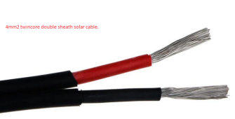
I use the 4mm sq twin core solar cable to the Anderson Plug.
Then I use 20Amp general purpose wire.
None of it gets hot at all.
It, now, makes me think this might slow down some of that initial "inrush current" as well.
Originally I tried much heavier wire but I found it too cumbersome.
So I tried the above & it seems to work well.
.
1681784358038.png
1681784165572.png
You obviously have had no issue for over 2 years now, so we are just trying to understand technically why that might be.
Hopefully my answers will shed some light.
If I am standing in a room full of dynamite with a lit match please let me know.
 
Last edited:
I will measure all 5 that I have - one is via a buck converter.

Thanks my understanding is improving - I think.

I use the 4mm sq twin core solar cable to the Anderson Plug.
Then I use 20Amp general purpose wire.
None of it gets hot at all.
It, now, makes me think this might slow down some of that initial "inrush current" as well.
Originally I tried much heavier wire but I found it too cumbersome.
So I tried the above & it seems to work well.
.
View attachment 145301
View attachment 145300

Hopefully my answers will shed some light.
If I am standing in a room full of dynamite with a lit match please let me know.
Can you estimate the length of the wires?
 
It’s possible that, when the system turns back on again as charger turns on, the current limit on the charger will limit the inrush current at that time even if the capacitors have decayed away all charge.
I had not realized this may be a problem.
I use dedicated Ampton LiFePo4 chargers designed by an ex Schneider technician Frick.
I also have no problem with the Victron Blue Smart Charger.
I thought maybe the 20AMp fuse & wires I use might create some resistance to the initial inrush.
I will be doing some readings for fafrd I think he wants these readings in relation to this.
.
1681790955710.png

I don’t have a full picture of how your specific setup works but this charger-based limiting idea (if it holds up) might be something others want to pursue, in combination with only switching on the AC side.
This is something I don't get.
What I am doing on these batteries, for grid connected systems, is cheap, portable, easy & quick.
It allows you to get one battery of any type & make use of it.
_ANY Battery & charger one side.
_ANY Battery protect in the middle.
_MicroInverter with timer the other side. (Micro Inverter types to be tested.)
I see all this expensive gear being discussed on this & other forums & my mind boggles.
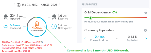
ALSO: With rearguard to the AC side I have responded to this:
.
1681802829014.png
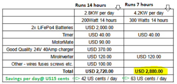
This simple robust system brand new (each) costs.
.
1681813935459.png
I’m curious if M250 and other microinverters report their idle DC side consumption. I’m not sure how much these would be optimized for AC down state, that’s supposed to be free power from the sun that would otherwise not be used.
Way above my understanding - I will research and learn as best I can.

Some of my working rues are:
It has to be something off the shelf that most people can afford.
Grid connected is best. IMO.
Forget efficiency - just add another panel. (easy if it is MicroInverters)
Forget optimisers if you didn't have them installed in the first pace - just add another panel.
Forget all the excess monitoring equipment use a multi-meter with a current clamp.
.
1681796446382.png
 
Last edited:
I don’t have a full picture of how your specific setup works but this charger-based limiting idea (if it holds up) might be something others want to pursue, in combination with only switching on the AC side.
A big thank you for this comment.
It makes me feel like my (albeit kind of misguided) work may have come to some good validity - after waiting a great deal of time.
You and a couple of others have shown good interest which pleases me no end.
I just hope it all stands up to scrutiny.
 
A big thank you for this comment.
It makes me feel like my (albeit kind of misguided) work may have come to some good validity - after waiting a great deal of time.
You and a couple of others have shown good interest which pleases me no end.
I just hope it all stands up to scrutiny.
The fact that you’ve already had two years of success running in this manner is already standing up to any scrutiny that you need to worry about.

There are two questions everyone is interested in:

1/ are the fears of damage to typical Microinverters when powering direct from battery unfounded? We won’t know the answer to that question definitely until we get some stories of failure among the several members attempting to follow in your footsteps (including me).

In the meantime, question 2 is related to particularities of the way you’ve built your rig which might have reduced or eliminated the risks most are worried about (which again, are not validated at this stage).

Your suggestion about resistance of your relay is a good one - knowing whatever specification it has for contact resistance along with the estimated + and - wire lengths of 4mm / 6 AWG wire you are using to connect between battery and Microinverter will help figure out what maximum inrush current you might be getting.

It’s amazing what impact as little as 10mOhms can have on inrush current…

By the way, you said 4mm wire but I assume that means standard 6AWG wire, correct?
 
So with regards to protecting the battery vs the inverter/other electronics.
  • The battery should be pretty fine with just regular battery fusing - that would protect against catastrophic short inside the inverter if something bad blows up.
  • However, a fuse will not directly protect the inverter (though adding some series resistance might provide some protection).
An interesting comparison here would be where a GTIL would make sense, and where a microinverter would make sense. I doubt any of the GTIL are up to modern grid spec (but they're probably fine for 2011 grid spec), and they have a bit more configuration flexibility with how much power they put out. It's easy to get microinverters for any modern grid spec you want, however they are natively limited to pushing out the max power unless you get one with export limiting features, which adds a decent chunk of expense. For Hoymiles about $300 if you just want to set % of maximum output, and $900 if you want automatic export limit.
 
The fact that you’ve already had two years of success running in this manner is already standing up to any scrutiny that you need to worry about.
Much Appreciated.
There are two questions everyone is interested in:

1/ are the fears of damage to typical Microinverters when powering direct from battery unfounded? We won’t know the answer to that question definitely until we get some stories of failure among the several members attempting to follow in your footsteps (including me).
OK. I hope their fears are unfounded especially if they operate at the lower end of the operating range.
I am keen to see others test this.
I will try to test others also.
Maybe we should have a list of MicroInverters tested so others can see results on each type.
In the meantime, question 2 is related to particularities of the way you’ve built your rig which might have reduced or eliminated the risks most are worried about (which again, are not validated at this stage).
OK...
Your suggestion about resistance of your relay is a good one - knowing whatever specification it has for contact resistance along with the estimated + and - wire lengths of 4mm / 6 AWG wire you are using to connect between battery and Microinverter will help figure out what maximum inrush current you might be getting.
Details at the end of this reply.
It’s amazing what impact as little as 10mOhms can have on inrush current…
I am staring to get a grip on this.
By the way, you said 4mm wire but I assume that means standard 6AWG wire, correct?
That is correct.
So with regards to protecting the battery vs the inverter/other electronics.
  • The battery should be pretty fine with just regular battery fusing - that would protect against catastrophic short inside the inverter if something bad blows up.
(y)
  • However, a fuse will not directly protect the inverter (though adding some series resistance might provide some protection).
Working out resistor sizes is not my forte.
An interesting comparison here would be where a GTIL would make sense, and where a microinverter would make sense. I doubt any of the GTIL are up to modern grid spec (but they're probably fine for 2011 grid spec), and they have a bit more configuration flexibility with how much power they put out. It's easy to get microinverters for any modern grid spec you want, however they are natively limited to pushing out the max power unless you get one with export limiting features, which adds a decent chunk of expense. For Hoymiles about $300 if you just want to set % of maximum output, and $900 if you want automatic export limit.
I would not do the GTIL - it adds too much complexity for what you pay IMO.
There are a lot of cheap second hand MicroInverters out there - I pay on average US $27 each for them & all mine are brand new.
At this stage it is miles cheaper to replace the MicroInverter - if one blows up IMO.
Already we are talking about switching on the AC side & ostensibly the MicroInverter will be subject to very few hits of inrush current and last much longer.

In Australia there are a number of factors for cheap MicroInverters as I see it.
1. Huge solar farms seem to be swapped out at the 10 year mark some of these have 100's of MicroInverters for sale - cheap.
2. Companies seem to buy a large excess of MicroInverters and have 100's of new ones left over which they dump.
3. There have been a lot of advancements E.G. IQ8 so, older models, even if new, are dumped.
4. Users are being convinced to change to string inverters.

I am not sure how your export limit works in the US ours is 5KW per household in Australia.
So I have two fan heaters stationed outside that I can set to pull 1.2KW, 2.4KW, 3.6KW or 4.8KW and pump out hot air.
During the hot months I set the Wi-Fi timer to burn 1.2KW for 4 hours during the middle of the day.
All the rest of the burning capacity, I have, is just backup.
I never export more that 3KW on any day.
I plan to use that energy so I don't just waste it. (Gas heater to electric, electric car ETC.)
This is another one of my working rules:
Produce as much solar power as you can. (cheaply) Worry about using it later.
So I have 8 more old panels & railing bought for USD $135 to put up.
I keep adding where / whenever I can.
 
Last edited:
Do you have any way to measure the stability of the current output from your PSU once it has stabilized?
Unfortunately I don't.
On the bench top power supply it stays on the amps & volts I set.
I’m curious whether a PSU feeding a Microinverter provides a relatively ‘safe’ / stable way to deliver a programmable amount if export from a Microinverter.
Yes it does.
I use my bench-top power supply to check my inverters often.
I have run the inverters all night no problem.
The claim is that the low-cost programmable DCDC boosters do not deliver a stable current but I’m hoping they are as stable as an AC-powered PSU…
This has not been my experience.
I found the DCDC boosters flaky.
Having said that I have had one (boost converter) running for two years an it runs, just, on hot.
 
Last edited:
Unfortunately I don't.

Yes it does.
I use my bench-top power supply to check my inverters often.
I have run the inverters all night no problem.

This has not been my experience.
I found the DCDC boosters flaky.
Having said that I have had one (boost converter) running for two years an it runs just on hot.
Flaky in terms of being difficult to set / configure using the pots, I understand.

And even ‘flaky’ in terms of the setting itself not being stable and needing to be recalibrated.

Both of those are different than the DC-DC-converter putting out much more current ripple than a standard bench top PSU…

Someone with an oscilloscope is going to have to make dons head-to-head measurements to understand what magnitude of current ripple we are talking about…

Your experience with your one DCDC converter suggests it may not be that big if a deal…
 
The fact that you’ve already had two years of success running in this manner is already standing up to any scrutiny that you need to worry about.
Much Appreciated.
There are two questions everyone is interested in:

1/ are the fears of damage to typical Microinverters when powering direct from battery unfounded? We won’t know the answer to that question definitely until we get some stories of failure among the several members attempting to follow in your footsteps (including me).
OK. I hope their fears are unfounded especially if they operate at the lower end of the operating range.
I can't wait until others test.
I will try to test other MicroInverters also.
Maybe we should have a list of MicroInverters tested so others can see what works & what doesn't.
In the meantime, question 2 is related to particularities of the way you’ve built your rig which might have reduced or eliminated the risks most are worried about (which again, are not validated at this stage).
OK...
Your suggestion about resistance of your relay is a good one - knowing whatever specification it has for contact resistance along with the estimated + and - wire lengths of 4mm / 6 AWG wire you are using to connect between battery and Microinverter will help figure out what maximum inrush current you might be getting.
Sorry.....I am unable to work out the inrush current - I wold need to learn that.
I will try.
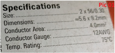
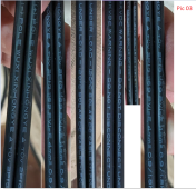
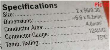
The first battery setup has 5 meters of 5.6mm cable (Pic 01.)
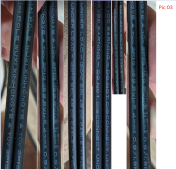
Then 0.5 metres of 2.4mm cable (Pic 02.)
The second battery setup has 1 metre of 4mm twin core cable. (Pic 03)
Then 0.5 metres of 2.4mm cable (Pic 02.)
The second battery setup has .6 metre of 4mm twin core cable. (Pic 03)
Then 0.5 metres of 2.4mm cable (Pic 02.)
.
1681884047250.png 1681884326013.png
1681887118578.png

It’s amazing what impact as little as 10mOhms can have on inrush current…
I am staring to get a grip on this.
By the way, you said 4mm wire but I assume that means standard 6AWG wire, correct?
That is correct.
Flaky in terms of being difficult to set / configure using the pots, I understand.

And even ‘flaky’ in terms of the setting itself not being stable and needing to be recalibrated.

Both of those are different than the DC-DC-converter putting out much more current ripple than a standard bench top PSU…

Someone with an oscilloscope is going to have to make dons head-to-head measurements to understand what magnitude of current ripple we are talking about…
I don't know how to use these.
I am looking forward to seeing results.
Your experience with your one DCDC converter suggests it may not be that big if a deal…
I have tried about 5 different types of DCDC converters.
The type I found best - I bought 4 of but I was unable to replicate.
I am pretty sure, now, it was because I was adjusting the Boost Converter in-situ.
Instead of adjusting the Boost Converter on a proper constant load, separately, the MPPT / Inverter were causing me all sorts of headaches whilst I was "trying" to adjust.
Hence my "flaky" claim.
The first Boost Converter was probably dumb luck.
Learning very slowly here.
 
Flaky in terms of being difficult to set / configure using the pots, I understand.
I don't think I understood what I was doing - the first Boost Converter was dumb luck I think.
But at least it encouraged me to go on.
And even ‘flaky’ in terms of the setting itself not being stable and needing to be recalibrated.
This is the mistake I made.
I should not have tried to calibrate it to the MPPT / Inverter.
Both of those are different than the DC-DC-converter putting out much more current ripple than a standard bench top PSU…
This is a bridge too far for my understanding.
I kind of get it.
Someone with an oscilloscope is going to have to make dons head-to-head measurements to understand what magnitude of current ripple we are talking about…
Looking forward to this.
Your experience with your one DCDC converter suggests it may not be that big if a deal…
I have put up more detail on this.
 
Can you estimate the length of the wires?
The first battery setup has 5 meters of 5.6mm cable (Pic 01.)
Then 0.5 metres of 2.4mm cable (Pic 02.)
The second battery setup has 1 metre of 4mm twin core cable. (Pic 03)
Then 0.5 metres of 2.4mm cable (Pic 02.)
The second battery setup has .6 metre of 4mm twin core cable. (Pic 03)
Then 0.5 metres of 2.4mm cable (Pic 02.)
.Pic 01.pngPic 02.pngPic 03.png
 
So with regards to protecting the battery vs the inverter/other electronics.
  • The battery should be pretty fine with just regular battery fusing - that would protect against catastrophic short inside the inverter if something bad blows up.
  • However, a fuse will not directly protect the inverter (though adding some series resistance might provide some protection).
I am working on a solution to this - I think I know what I am doing.
An interesting comparison here would be where a GTIL would make sense, and where a microinverter would make sense. I doubt any of the GTIL are up to modern grid spec (but they're probably fine for 2011 grid spec), and they have a bit more configuration flexibility with how much power they put out. It's easy to get microinverters for any modern grid spec you want, however they are natively limited to pushing out the max power unless you get one with export limiting features, which adds a decent chunk of expense. For Hoymiles about $300 if you just want to set % of maximum output, and $900 if you want automatic export limit.
2nd hand MicroInverters are dead cheap.
If ever one blows just replace it. IMO
Once we have a list of MicroInverters that work users can buy any on the list.
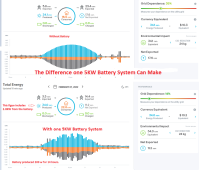
This is hoping that this idea works and we get a section under Energy Storage in DIYSolarForum just to deal with this.
It would be an easy way for just about anyone to get into Battery Storage.
.
One Battery System.png
 
So i've now tested a PWM unit onto the inverter input...

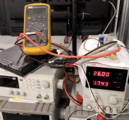
Overall, it does what it says on the tin. With the PSU set for 26v/5A and the multimeter monitoring Vin of the inverter you can start at zero PWM and zero volts, add a little duty and the multimeter voltage rapidly comes up to about 25.5. The inverter powers up, checks the grid then after a few mins switches into production mode. At this point the voltage drops and hovers around 16v (near the turn-on point of the inverter). You can wind the PWM up and down and the input current (as measured by the PSU) goes up and down pretty nicely - it was stable at 0.2A dc. If you crank the PWM up i can easily hit the current limit of the PSU, at which point the PSU voltage drops as well. It looks like it would be pretty easy to control power output with an arduino or similar as the response seemed linear and predictable.
The multimeter voltage does hover about the 16-16.5v area with occasional excursions to ~22v when tuning the power up/down. This is below the MPPT point of the inverter. I wasn't sure what to expect with this but it seems the inverter drags the voltage down near the turnoff point then modulates the power so it doesn't turn off / to suit the input power.

All good so far, but one of the transistors on the PWM board did get very hot to the touch with just a few minutes running so i'm not sure how durable the setup is, although i am quite tempted to find out.
Do any of the more knowledgeable members have any idea if this temperature is OK, or if not how i could reduce it? I did wonder about an inductor on the PWM output to smooth things out a bit...
 

Attachments

  • Inverter PWM.PNG
    Inverter PWM.PNG
    688.6 KB · Views: 5
So i've now tested a PWM unit onto the inverter input...

Overall, it does what it says on the tin. With the PSU set for 26v/5A and the multimeter monitoring Vin of the inverter you can start at zero PWM and zero volts, add a little duty and the multimeter voltage rapidly comes up to about 25.5. The inverter powers up, checks the grid then after a few mins switches into production mode. At this point the voltage drops and hovers around 16v (near the turn-on point of the inverter). You can wind the PWM up and down and the input current (as measured by the PSU) goes up and down pretty nicely - it was stable at 0.2A dc. If you crank the PWM up i can easily hit the current limit of the PSU, at which point the PSU voltage drops as well. It looks like it would be pretty easy to control power output with an arduino or similar as the response seemed linear and predictable.
The multimeter voltage does hover about the 16-16.5v area with occasional excursions to ~22v when tuning the power up/down. This is below the MPPT point of the inverter. I wasn't sure what to expect with this but it seems the inverter drags the voltage down near the turnoff point then modulates the power so it doesn't turn off / to suit the input power.

All good so far, but one of the transistors on the PWM board did get very hot to the touch with just a few minutes running so i'm not sure how durable the setup is, although i am quite tempted to find out.
Do any of the more knowledgeable members have any idea if this temperature is OK, or if not how i could reduce it? I did wonder about an inductor on the PWM output to smooth things out a bit...
Yes I tried various PWM devices.
They all got too hot or fried.
Just to be clear I am not sure what I was doing.
Looks like you have the same MicroInverter I have.
You can just plug it in to the bench top power supply without the PWM.
Set it at 24-29V & 8Amp.
You can ramp it up from there.
I have done this with Enphase & SunnyBoy Micro Inverters, for days, loads of times.
If you are worried about frying it let me know the cost.
I will pay, at least, 1/2 the cost or maybe the full cost. (If it gets fried)
I need to know the cost of it FIRST.
Then I will tell you what $ I will put toward it.
I'm not worried about frying the inverter or PSU, i think based on what you've done they will be fine - that is why i bought an Enphase to play with based on your good results!

What i need to do is reduce the inverter output - if i run it direct off a 24v battery it will make ~250w ac, i only want to make 100-150w ac to cover my night-time usage. The difference doesn't sound like much but it is half the battery capacity needed! Unless you know of any smaller reputable inverters?
OK. That is difficult.
I notice in Australia the energy meters calculate by the 1/2 hour to one hour - not by minutes.
So if you use 1 KW at the beginning of the hour & put back 1KW before the end of the hour the meter will show zero consumption.
I think it would be the same in the UK.
Please let me know if I am mistaken.
The, very common, timers I pointed out are programmable to do 8 On then Offs per day.
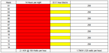
To get started you could program the Inverter to come on & off for 8 times per night.
I have done a rough spreadsheet at 1 hour intervals just for show.
You could calculate something much better than what I have.
You would have better ideas & timings but this will not hurt to get your show on the road. IMO
.
1681906072864.png
 
Last edited:
OK. That is difficult.
I notice in Australia the energy meters calculate by the 1/2 hour to one hour - not by minutes.
So if you use 1 KW at the beginning of the hour & put back 1KW before the end of the hour the meter will show zero consumption.
I think it would be the same in the UK.
Please let me know if I am mistaken.
The, very common, timers I pointed out will do 8 On then Offs.
To get started you could program the Inverter to come on & off for 8 times per night.
I have done a rough spreadsheet at 1 hour intervals just for show.
You could calculate something much better than what I have.
You would have better ideas & timings but this will not hurt to get your show on the road. IMO
.
View attachment 145509
Unfortunately UK electricity meters don't work exactly like that... they use an energy 'bucket' that contains 3600J (one Watt-hour), every time you empty it by using the energy it increments the counter for billing, so you need to be accurate and fast.

I also have a device to divert excess AC power to my immersion heater, this has to use individual ac wave control to cope with the above - e.g for a 3kw heater you want to run at 5% (150w) it activates 1 in 20 full ac waves.....the solar then replenishes the 'bucket' before the heater fires again so you don't increment the billing counter.

I think i'm just going to try the PWM controller and see how long it lasts, and maybe an inductor on the output before the inverter as well.

Failing that, i may also try plan B, with a DC SSR switched at about 500-1000Hz but they're about £50 so i don't want to do that just yet...
OK. Was worth a shot.
 
So i've now tested a PWM unit onto the inverter input...

Overall, it does what it says on the tin. With the PSU set for 26v/5A and the multimeter monitoring Vin of the inverter you can start at zero PWM and zero volts, add a little duty and the multimeter voltage rapidly comes up to about 25.5. The inverter powers up, checks the grid then after a few mins switches into production mode. At this point the voltage drops and hovers around 16v (near the turn-on point of the inverter). You can wind the PWM up and down and the input current (as measured by the PSU) goes up and down pretty nicely - it was stable at 0.2A dc. If you crank the PWM up i can easily hit the current limit of the PSU, at which point the PSU voltage drops as well. It looks like it would be pretty easy to control power output with an arduino or similar as the response seemed linear and predictable.
The multimeter voltage does hover about the 16-16.5v area with occasional excursions to ~22v when tuning the power up/down. This is below the MPPT point of the inverter. I wasn't sure what to expect with this but it seems the inverter drags the voltage down near the turnoff point then modulates the power so it doesn't turn off / to suit the input power.

All good so far, but one of the transistors on the PWM board did get very hot to the touch with just a few minutes running so i'm not sure how durable the setup is, although i am quite tempted to find out.

Do any of the more knowledgeable members have any idea if this temperature is OK, or if not how i could reduce it? I did wonder about an inductor on the PWM output to smooth things out a bit...
The higher-powered DCDC converters come with integrated fans and all of them stare you need to increase ventilation to go above ~half of maximum power rating, so I’d think using a computer fan to blow down into the PWM heatsink is the first thing to try if you want to extend lifetime while pushing it…
 
Back
Top