kundip
Micro Inverter Enthusiast
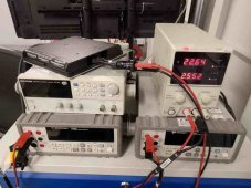
These are the cheapo DCDC boosters I’m going to be experimenting with:
View attachment 143196
They have two potentiometers hard-wired in for control, one to set current limit and one to set voltage limit,
Any idea whether a design using a wired-in (settable) resistor can suffer from the uncontrolled boost you experienced?
I suppose adding a monitor circuit to shut everything down if any boost voltage exceeds 150% or even 125% of target wouldn’t be the end of the world…
You are still talking about charging a phone, or is that somehow relative to the thread topic?
Sounds like more phone charging stuff. Appreciate any input you have on how to prevent against the possibility of a DC-DC boost converter exceeding the maximum input voltage rating of a Microinverter, but the subject of charging mobile phones or any other electronics for that matter is really not relevant to the subject of this thread…
These are the cheapo DCDC boosters I’m going to be experimenting with:These are the cheapo DCDC boosters I’m going to be experimenting with:
View attachment 143196
They have two potentiometers hard-wired in for control, one to set current limit and one to set voltage limit,
Any idea whether a design using a wired-in (settable) resistor can suffer from the uncontrolled boost you experienced?
I suppose adding a monitor circuit to shut everything down if any boost voltage exceeds 150% or even 125% of target wouldn’t be the end of the world…
You are still talking about charging a phone, or is that somehow relative to the thread topic?
Sounds like more phone charging stuff. Appreciate any input you have on how to prevent against the possibility of a DC-DC boost converter exceeding the maximum input voltage rating of a Microinverter, but the subject of charging mobile phones or any other electronics for that matter is really not relevant to the subject of this thread…
_I have some notes here:
_https://diysolarforum.com/threads/u...-batteries-instead-of-panels.8353/post-753344
They have two potentiometers hard-wired in for control, one to set current limit and one to set voltage limit,
Any idea whether a design using a wired-in (settable) resistor can suffer from the uncontrolled boost you experienced?
_I swapped out the potentiomers for much better ones but it did not help in my case.
I suppose adding a monitor circuit to shut everything down if any boost voltage exceeds 150% or even 125% of target wouldn’t be the end of the world…
_This is not an area I have researched. The MicroInverter may have some sort of surge protection.
_You have a good range to play with 22V to 36V plus. You don't have to use the highest voltage 24V gives you some room for surges.
_With a direct battery connect you should not have to worry about having a monitor circuit or the buck or boost converter.
") .
.