diy solar

diy solar

Using solar micro inverters with batteries instead of panels

Flaky in terms of being difficult to set / configure using the pots, I understand.
I don't think I understood what I was doing - the first Boost Converter was dumb luck I think.
But at least it encouraged me to go on.
And even ‘flaky’ in terms of the setting itself not being stable and needing to be recalibrated.
This is the mistake I made.
I should not have tried to calibrate it to the MPPT / Inverter.
Both of those are different than the DC-DC-converter putting out much more current ripple than a standard bench top PSU…
This is a bridge too far for my understanding.
I kind of get it.
Someone with an oscilloscope is going to have to make dons head-to-head measurements to understand what magnitude of current ripple we are talking about…
Looking forward to this.
Your experience with your one DCDC converter suggests it may not be that big if a deal…
I have put up more detail on this.
 
Can you estimate the length of the wires?
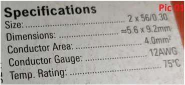
The first battery setup has 5 meters of 5.6mm cable (Pic 01.)
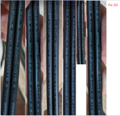
Then 0.5 metres of 2.4mm cable (Pic 02.)
The second battery setup has 1 metre of 4mm twin core cable. (Pic 03)
Then 0.5 metres of 2.4mm cable (Pic 02.)
The second battery setup has .6 metre of 4mm twin core cable. (Pic 03)
Then 0.5 metres of 2.4mm cable (Pic 02.)
.Pic 01.pngPic 02.pngPic 03.png
 
So with regards to protecting the battery vs the inverter/other electronics.
  • The battery should be pretty fine with just regular battery fusing - that would protect against catastrophic short inside the inverter if something bad blows up.
  • However, a fuse will not directly protect the inverter (though adding some series resistance might provide some protection).
I am working on a solution to this - I think I know what I am doing.
An interesting comparison here would be where a GTIL would make sense, and where a microinverter would make sense. I doubt any of the GTIL are up to modern grid spec (but they're probably fine for 2011 grid spec), and they have a bit more configuration flexibility with how much power they put out. It's easy to get microinverters for any modern grid spec you want, however they are natively limited to pushing out the max power unless you get one with export limiting features, which adds a decent chunk of expense. For Hoymiles about $300 if you just want to set % of maximum output, and $900 if you want automatic export limit.
2nd hand MicroInverters are dead cheap.
If ever one blows just replace it. IMO
Once we have a list of MicroInverters that work users can buy any on the list.
This is hoping that this idea works and we get a section under Energy Storage in DIYSolarForum just to deal with this.
It would be an easy way for just about anyone to get into Battery Storage.
.
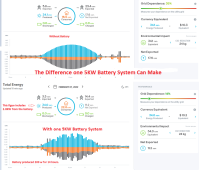
One Battery System.png
 
So i've now tested a PWM unit onto the inverter input...

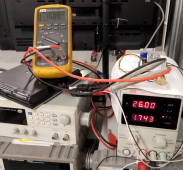
Overall, it does what it says on the tin. With the PSU set for 26v/5A and the multimeter monitoring Vin of the inverter you can start at zero PWM and zero volts, add a little duty and the multimeter voltage rapidly comes up to about 25.5. The inverter powers up, checks the grid then after a few mins switches into production mode. At this point the voltage drops and hovers around 16v (near the turn-on point of the inverter). You can wind the PWM up and down and the input current (as measured by the PSU) goes up and down pretty nicely - it was stable at 0.2A dc. If you crank the PWM up i can easily hit the current limit of the PSU, at which point the PSU voltage drops as well. It looks like it would be pretty easy to control power output with an arduino or similar as the response seemed linear and predictable.
The multimeter voltage does hover about the 16-16.5v area with occasional excursions to ~22v when tuning the power up/down. This is below the MPPT point of the inverter. I wasn't sure what to expect with this but it seems the inverter drags the voltage down near the turnoff point then modulates the power so it doesn't turn off / to suit the input power.

All good so far, but one of the transistors on the PWM board did get very hot to the touch with just a few minutes running so i'm not sure how durable the setup is, although i am quite tempted to find out.
Do any of the more knowledgeable members have any idea if this temperature is OK, or if not how i could reduce it? I did wonder about an inductor on the PWM output to smooth things out a bit...
 

Attachments

  • Inverter PWM.PNG
    Inverter PWM.PNG
    688.6 KB · Views: 5
So i've now tested a PWM unit onto the inverter input...

Overall, it does what it says on the tin. With the PSU set for 26v/5A and the multimeter monitoring Vin of the inverter you can start at zero PWM and zero volts, add a little duty and the multimeter voltage rapidly comes up to about 25.5. The inverter powers up, checks the grid then after a few mins switches into production mode. At this point the voltage drops and hovers around 16v (near the turn-on point of the inverter). You can wind the PWM up and down and the input current (as measured by the PSU) goes up and down pretty nicely - it was stable at 0.2A dc. If you crank the PWM up i can easily hit the current limit of the PSU, at which point the PSU voltage drops as well. It looks like it would be pretty easy to control power output with an arduino or similar as the response seemed linear and predictable.
The multimeter voltage does hover about the 16-16.5v area with occasional excursions to ~22v when tuning the power up/down. This is below the MPPT point of the inverter. I wasn't sure what to expect with this but it seems the inverter drags the voltage down near the turnoff point then modulates the power so it doesn't turn off / to suit the input power.

All good so far, but one of the transistors on the PWM board did get very hot to the touch with just a few minutes running so i'm not sure how durable the setup is, although i am quite tempted to find out.
Do any of the more knowledgeable members have any idea if this temperature is OK, or if not how i could reduce it? I did wonder about an inductor on the PWM output to smooth things out a bit...
Yes I tried various PWM devices.
They all got too hot or fried.
Just to be clear I am not sure what I was doing.
Looks like you have the same MicroInverter I have.
You can just plug it in to the bench top power supply without the PWM.
Set it at 24-29V & 8Amp.
You can ramp it up from there.
I have done this with Enphase & SunnyBoy Micro Inverters, for days, loads of times.
If you are worried about frying it let me know the cost.
I will pay, at least, 1/2 the cost or maybe the full cost. (If it gets fried)
I need to know the cost of it FIRST.
Then I will tell you what $ I will put toward it.
I'm not worried about frying the inverter or PSU, i think based on what you've done they will be fine - that is why i bought an Enphase to play with based on your good results!

What i need to do is reduce the inverter output - if i run it direct off a 24v battery it will make ~250w ac, i only want to make 100-150w ac to cover my night-time usage. The difference doesn't sound like much but it is half the battery capacity needed! Unless you know of any smaller reputable inverters?
OK. That is difficult.
I notice in Australia the energy meters calculate by the 1/2 hour to one hour - not by minutes.
So if you use 1 KW at the beginning of the hour & put back 1KW before the end of the hour the meter will show zero consumption.
I think it would be the same in the UK.
Please let me know if I am mistaken.
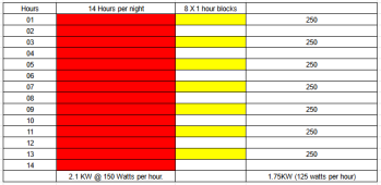
The, very common, timers I pointed out are programmable to do 8 On then Offs per day.
To get started you could program the Inverter to come on & off for 8 times per night.
I have done a rough spreadsheet at 1 hour intervals just for show.
You could calculate something much better than what I have.
You would have better ideas & timings but this will not hurt to get your show on the road. IMO
.
1681906072864.png
 
Last edited:
OK. That is difficult.
I notice in Australia the energy meters calculate by the 1/2 hour to one hour - not by minutes.
So if you use 1 KW at the beginning of the hour & put back 1KW before the end of the hour the meter will show zero consumption.
I think it would be the same in the UK.
Please let me know if I am mistaken.
The, very common, timers I pointed out will do 8 On then Offs.
To get started you could program the Inverter to come on & off for 8 times per night.
I have done a rough spreadsheet at 1 hour intervals just for show.
You could calculate something much better than what I have.
You would have better ideas & timings but this will not hurt to get your show on the road. IMO
.
View attachment 145509
Unfortunately UK electricity meters don't work exactly like that... they use an energy 'bucket' that contains 3600J (one Watt-hour), every time you empty it by using the energy it increments the counter for billing, so you need to be accurate and fast.

I also have a device to divert excess AC power to my immersion heater, this has to use individual ac wave control to cope with the above - e.g for a 3kw heater you want to run at 5% (150w) it activates 1 in 20 full ac waves.....the solar then replenishes the 'bucket' before the heater fires again so you don't increment the billing counter.

I think i'm just going to try the PWM controller and see how long it lasts, and maybe an inductor on the output before the inverter as well.

Failing that, i may also try plan B, with a DC SSR switched at about 500-1000Hz but they're about £50 so i don't want to do that just yet...
OK. Was worth a shot.
 
So i've now tested a PWM unit onto the inverter input...

Overall, it does what it says on the tin. With the PSU set for 26v/5A and the multimeter monitoring Vin of the inverter you can start at zero PWM and zero volts, add a little duty and the multimeter voltage rapidly comes up to about 25.5. The inverter powers up, checks the grid then after a few mins switches into production mode. At this point the voltage drops and hovers around 16v (near the turn-on point of the inverter). You can wind the PWM up and down and the input current (as measured by the PSU) goes up and down pretty nicely - it was stable at 0.2A dc. If you crank the PWM up i can easily hit the current limit of the PSU, at which point the PSU voltage drops as well. It looks like it would be pretty easy to control power output with an arduino or similar as the response seemed linear and predictable.
The multimeter voltage does hover about the 16-16.5v area with occasional excursions to ~22v when tuning the power up/down. This is below the MPPT point of the inverter. I wasn't sure what to expect with this but it seems the inverter drags the voltage down near the turnoff point then modulates the power so it doesn't turn off / to suit the input power.

All good so far, but one of the transistors on the PWM board did get very hot to the touch with just a few minutes running so i'm not sure how durable the setup is, although i am quite tempted to find out.

Do any of the more knowledgeable members have any idea if this temperature is OK, or if not how i could reduce it? I did wonder about an inductor on the PWM output to smooth things out a bit...
The higher-powered DCDC converters come with integrated fans and all of them stare you need to increase ventilation to go above ~half of maximum power rating, so I’d think using a computer fan to blow down into the PWM heatsink is the first thing to try if you want to extend lifetime while pushing it…
 
Yes I tried various PWM devices.
They all got too hot or fried.
Just to be clear I am not sure what I was doing.
Looks like you have the same MicroInverter I have.
You can just plug it in to the bench top power supply without the PWM.
Set it at 24-29V & 8Amp.
You can ramp it up from there.
I have done this with Enphase & SunnyBoy Micro Inverters, for days, loads of times.
If you are worried about frying it let me know the cost.
I will pay, at least, 1/2 the cost or maybe the full cost. (If it gets fried)
I need to know the cost of it FIRST.
Then I will tell you what $ I will put toward it.
Here is a post showing the capacitors on a higher-quality High-Frequency inverter and a low-quality High Frequency inverter: https://diysolarforum.com/threads/not-to-happy-with-magnum.44313/page-3#post-752607

If/when you fry one of your Enphase microinverters, it would be very interesting to know what kind of capacitors it has connected to the DC inputs… (an open call to anyone else who may have a dead Enphase Microinverter).

I have not gone to the trouble of tracing out the circuit to confirm they are connected to the DC inputs, but my single-MPPT-dual-MC4-inout 590W NEP Microinverters contain 8 large 2700uF 63V capacitors that also say 105C.

So just as a placeholder, 8x2700uF = 21,600uF and charging that to 25VDC through a 100mOhm resistance, that would mean an RC time constant 21.6ms, meaning the input is charged to ~12.5VDC after 15.12ms and is fully charged to 25V after 108ms.

Someone with more understanding than I needs to comment on whether this degree of startup surge upon connection looks like anything to be concerned about.

The other concern that has been voiced regarding the use of DC DC converters is high-frequency current ripple heating up the input capacitors.

Page 55 here has the specs for my Samxon GS(R) series capacitors: https://datasheet.lcsc.com/lcsc/2208091800_Man-Yue-Tech-ESK827M1JI30RR_C5123348.pdf

But someone with more knowledge than I of how to interpret capacitor ripple specifications will need to tell me what level of current ripple is likely to overheat and damage 4x2700uF of these capacitors…

(At least I know my dinky 590W Microinverters have 50% more input capacitance than Deye is putting on their higher-end Hybrid Inverters! (8x2700=21,600uF versus 14x1000uF = 14,000uF on the Deye).
 
Last edited:
According to the spec sheet and label on the board it is voltage controlled...a big reason I want to try this one.

I like the idea of a parallel resistance to precharge the output...I have planned on capacitors to smooth the output, doing a very quick calc using 24v, 10a and 1/15000s I get 0.02j per cycle, so I've picked electrolytic caps that store 10x that energy: 1000uf, and I've ordered 5 of them...I'm hoping that 5percent ripple is ok for the inverter but I'll find out one way or another...

I just posted that my Microinverters have 8x 2700uF = 21,600uF of capacitance on their dual inputs. And TI’s chip seems to claim 2% max ripple on output of it’s DC-DC booster (no idea what chip is being used by the cheapo DCDC boosters).

So if your PWM were feeding my Microinverters, the 5000uF you are adding would only reduce ripple by ~33% versus what it would be without them.

And while ripple on your PWM (switching at what frequency?) would no doubt be much worse than that delivered by a DCDC booster, you may be under 5% just relying on the Microinverters DC input capacitance…

What Microinverters are you using?
I've not got a scope although I can probably borrow one if I can't get it working very easily.
I have no idea if these work at all: https://www.amazon.com/gp/aw/d/B09Q13TWY4/ref=ox_sc_saved_image_4?smid=A1VTL661FOEJB1&psc=1

But I’m planning to pick one up when I’ve got ripple to characterize. If it doesn’t work well enough to see the ripple at the magnitude I’m looking for, it will go back to Amazon for a refund…
 
But someone with more knowledge than I of how to interpret capacitor ripple specifications will need to tell me what level of current ripple is likely to overheat and damage 4x2700uF of these capacitors…
You can probably ask someone on the circuit analysis forums to guide you through this (analysis and implementing a compensating circuit), I think I've seen questions like this on r/askelectronics
 
Interesting overview of nighttime consumption of Enphase Microinverters (applicable to any inverter):

He says nothing about the DC input capacitance but Enphase inverters apparently have 3 330nF capacitors across the AC output wires (so 990nF per Microinverter).

Not terribly relevant to our current discussion (no pun intended ;)), but at least it confirms that the 8 x 2700uF caps I see in my NEP 590W dual Microinverters are on the DC input.
Thanks for this.
It is assisting me to gain more knowlege & understanding.
 
Thanks for this.
It is assisting me to gain more knowlege & understanding.
You should reach out to him and invite him over to check out your setup - if you convince him to do a segment on what you’ve put together, that’ll really get the word out!
 
I just posted that my Microinverters have 8x 2700uF = 21,600uF of capacitance on their dual inputs. And TI’s chip seems to claim 2% max ripple on output of it’s DC-DC booster (no idea what chip is being used by the cheapo DCDC boosters).

So if your PWM were feeding my Microinverters, the 5000uF you are adding would only reduce ripple by ~33% versus what it would be without them.

And while ripple on your PWM (switching at what frequency?) would no doubt be much worse than that delivered by a DCDC booster, you may be under 5% just relying on the Microinverters DC input capacitance…

What Microinverters are you using?

I have no idea if these work at all: https://www.amazon.com/gp/aw/d/B09Q13TWY4/ref=ox_sc_saved_image_4?smid=A1VTL661FOEJB1&psc=1

But I’m planning to pick one up when I’ve got ripple to characterize. If it doesn’t work well enough to see the ripple at the magnitude I’m looking for, it will go back to Amazon for a refund…
I'm using Enphase M250 inverters, the PWM is switching at 15kHz. The inverter runs fine with no additional input capacitance which supports your observation that there is already plenty in the inverter.

After looking at some youtube reviews i've also just ordered a 20a PWM module / 25kHz, the guy reviews it and loads it up, it runs cool at 10A continuous which is what i need so that could be better for my use...we'll see.

Thanks for the amazon link, that looks interesting - i might get one of those scopes to try. I do also have a 150000uf 100v capacitor i could use to smooth things out, i might give that a try, i'm also interested in trying an inductor inline as well but haven't ordered anything yet..
 
I'm using Enphase M250 inverters, the PWM is switching at 15kHz. The inverter runs fine with no additional input capacitance which supports your observation that there is already plenty in the inverter.

After looking at some youtube reviews i've also just ordered a 20a PWM module / 25kHz, the guy reviews it and loads it up, it runs cool at 10A continuous which is what i need so that could be better for my use...we'll see.
A link to those reviews would be great.

So if you want to run your M250 at 125W, you’d run your 20A PWM at 25% duty cycle off of a 25V battery, right?

And switching at 25kHz will cause only 60% of the ripple you get when switching at 15kHz.

For reference, switching the 21,600uF of my Microinverters with 20A at 25kHz @ 25% duty-cycle means 20A for 10uS or 0.2 milliCoulomb per cycle which should result in voltage ripple of ~10mV or 0.04% of 25VDC…

Of course, the real question is what is the impedance of those input capacitors at 25kHz and how much heat gets generated by pushing and pulling 0.2 milliCoulombs into and out of them at that frequency…

Thanks for the amazon link, that looks interesting - i might get one of those scopes to try. I do also have a 150000uf 100v capacitor i could use to smooth things out, i might give that a try, i'm also interested in trying an inductor inline as well but haven't ordered anything yet..
Please let us know if you do - my advice is don’t purchase until you have something ready to test. That gives you 30 days to figure out whether the scope is junk or worth the $45…
 
Thanks. At 10A / 50% duty cycle, seems like you should have little to worry about (at least as fas as the PWM being able to handle it).

I suspect the ripple you see is going to be very small and other than getting the specs on the input capacitors and doing dons analysis, you may have no choice other than running your Microinverter with it in the interests of science.

Since it’ll take two years to know whether the 20-year lifetime was reduced by 90%, I think there is a good chance this PWM rig will work as well the two kundip has been using..
 
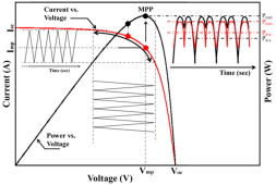
Microinverters have no problem dealing with 50/60Hz current and voltage ripple:

779CD278-13CC-43D7-860D-107A9AD78F9E.png
What I’m unable to wrap my head around is whether 25kHz PWM current ripple layered on top of the range between these two operating extremes can cause a problem with overheating the input capacitors…

At 20A @ 50% duty cycle, the shorter-duration current ripple from the PWM controller is more than double absolute current magnitude of the 50/60Hz current ripple that would be coming from a solar panel…

The main reason I’m raising this issue is that we now know that kundip has a DC relay between battery and Microinverter (or DCDC converter and Microinverter), and it’s conceivable the ~100mOhm inline contact resistance of that relay is critical to making his system work.

So you might want to think about using a relay as well or a 100mOhm resistance between PWM and inverter…

At 125W of outout power, an average of 5A through 100mOhm would represent 2.5W or 2%…

Cranked up to 250W if output power, an average of 10A through 100mOhm would represent 10W or 4%…

If you get everything working with a 100mOhm series resistance first and then start reducing that series resistance and eventually eliminating, if it stops working at some point, at least you’ll understand why.

By the way, I found these 50W 100 milliOhm resistors on Amazon: https://www.amazon.com/Resistors-Wirewound-Resistor-Replacement-Converter/dp/B0936VMYJF
 
Last edited:
I do also have a 150000uf 100v capacitor i could use to smooth things out, i might give that a try, i'm also interested in trying an inductor inline as well but haven't ordered anything yet..
So just as a thought exercise, if you connect your 150,000uF capacitor to the Microinverter input and connect the PWM through a 0.1 Ohm resistor, that would translate to an RC time constant of 1.5mS, meaning 7.5ms to reach 99% of equilibrium voltage.

If you are on 60Hz grid, 7.5ms is 45% of total period or 90% of a half-period, so that’s probably about the limit of what might work without losing too much efficiency.

There are 0.05 Ohm and even 0.02 Ohm power resistors which can speed up the 60Hz switching time to 99% to 3.75 or even 1.5ms but you would probably want to check what voltages the MPPT of the Microinverter settles on to get a sense of how many Watts are flowing at the beginning of the transients to be sure you are getting meaty enough resistors.

If the Microinverter was switching between a worst-case of 25VDC for close to 0A and the voltage that delivers 10A for the other half-cycle, 10A x 0.02 Ohms = 0.2V meaning 24.8VDC.

If the worst case voltage drop across an 0.02 Ohm resistor is 0.2V, word-case current is 10A and worst-case power is 2 watts (I^2R).

In that situation, you could probably get by with a 3W 0.02W current sense resistor like this: https://www.amazon.com/Ohmite-Current-Sense-Resistor-0-02/dp/B00DEE94UQ

As I think through it some more, that massive 150,000uF capacitor you have is a fantastic way to characterize exactly what your M250 Microinverter MPPT is doing (assuming you have a simple scope that can capture at at least 1kHz or ideally 100KHz).
 
Since I’m throwing out crazy ideas, I thought I’d add another one.

The risk of powering any Microinverter from a switched DC supply such as a PWM is that the high-frequency current ripple heats up and wears out the input capacitors of the Microinverter prematurely.

kundip has proven that this premature wear out is unlikely to be a concern for at least 2 years (at least when powered by a DCDC converter through a DC relay).

The 25kHz PWM controller you are using should be a worst-worst case as far as introducing high-frequency current ripple that does not exist when powering a Microinverter from a solar panel.

The massive 100,000uF capacitor you have is fantastic for characterization but not practical for an Everyman solution (too costly).

But 10,000uF capacitors of the same class as those used on the input of Microinverters are not prohibitively costly: https://www.amazon.com/Ohmite-Current-Sense-Resistor-0-02/dp/B00DEE94UQ

So my latest thought is ‘why not use one of these 10,000uF capacitors as a canary to protect the Microinverter?’

If the PWM is connected to one of these 10,000uF 63V capacitors before connecting through an 0.1, 0.05, or 0.02 Ohm resistor to a Microinverter input with 21,600uF or 10,800uF of 63V input capacitance of its own, the 10,000uF capacitor has got to see far more current ripple at 25kHz than the input capacitors, so if that level of PWM-induced 25kHz current ripple is an issue, the 10,000uF capacitor should burn out far before any of the Microinverter’s input capacitors.

An idealized model would have the MPPT of the Microinverter switching between 25V and 24.8V @ 60Hz for 125W of input power (through a 100mOhm resistor), while the PWM maintains an output averaging 24.8 V for 16.7mS followed by 25.0V for 16.7mS by pushing out 10A for 20uS followed by pushing out 0A for 20uS (so 5A of output current on average).

The Microinverter is also Maintaining an average input current of 5A but at 60Hz, drawing 10A for 16.7mS while the MPPT puts 24.8V on the input followed by 0A for 16.7ms while the MPPT puts 25.0V on the input and the PWM gets it’s output charged up to 25.0V as well (in 20uS steps every 40uS).

Worst-case currents across the 0.1 Ohm resistor (and hence the input capacitors) at 25kHz would be 0.2V / 0.1Ohm = 2A for 20uS, but that current is primarily stepping PWM output voltage up to 25.0V and then down to 24.8V @ 60Hz, so 25KHz current ripple impacting the input capacitors is much less…

In fact, now that I think about it, the input capacitance at 25.0V will draw current across the 100mOhm resistor when the MPPT drops voltage to 24.8V so the vast majority of ripple current on the input capacitors will be at 60Hz, as it is in the case of being powered by a solar panel…
 
You should reach out to him and invite him over to check out your setup - if you convince him to do a segment on what you’ve put together, that’ll really get the word out!
Dave wrote back & said he cannot do it.
He has too much work on & family commitments.
I offered to pay for the 6,400KM round trip including his fees, accommodation & food.
No luck.
Thanks for the suggestion.
 
Last edited:

diy solar

diy solar
Back
Top