diy solar

diy solar

Using solar micro inverters with batteries instead of panels

I'm UK based, I do have an officially installed solar system that came with the house when I bought it. It's on an old/good generation tariff where there is a separate meter and I get paid on everything generated regardless if I use it or not. But it does mean I can't modify the system or tap off DC power.
Basically I want to do AC storage so I can reduce my bill and use everything I generate..

Arduino isn't really os based, it's much more like a plc but more codeable. And I'm probably going to do a hardware watchdog to shut everything down if the controller freezes...
Way to go.
Bye the bye.
I think no one can stop you putting up solar panels to charge batteries.
 
These PWM controllers also warn you about excess heat when running beyond 50% of max rating for a sustained period, but they are apparently starting from an efficiency of ~95% rather than 85%…

That’s 1/3rd the heat generation and it’s the reason the higher-powered DCSC-converters have much more serious heatsinks and even integrated fans compared to the PWM controllers.

I would be pretty upset if PWM had efficiency < 95%. It only needs a switching transistor and it probably has zero isolation (seeing as it operates at a single voltage) so overall is super simple.

DC DC converters need considerably more parts inside them -- blocking diodes, inductors, capacitors, etc. carrying significant levels of power.

Regarding the ripple discussion. There is a frequency component to this. Both in terms of the total current and the ripple current that a capacitor is rated to handle: https://www.vishay.com/docs/40057/ldacripp.pdf https://www.eevblog.com/forum/proje...-current-cap-that-isnt-physically-very-large/
From the handful of threads and spec sheets I looked at, for capacitors optimized for SMPS higher frequency is better. I don't know what kind of capacitor is in the microinverter.
 
I would be pretty upset if PWM had efficiency < 95%. It only needs a switching transistor and it probably has zero isolation (seeing as it operates at a single voltage) so overall is super simple.
I2R gets you coming and it gets you going. The YouTube videos where they characterize efficiency, I’m not sure they model the losses from whatever wiring they are using.
DC DC converters need considerably more parts inside them -- blocking diodes, inductors, capacitors, etc. carrying significant levels of power.

Regarding the ripple discussion. There is a frequency component to this. Both in terms of the total current and the ripple current that a capacitor is rated to handle: https://www.vishay.com/docs/40057/ldacripp.pdf https://www.eevblog.com/forum/proje...-current-cap-that-isnt-physically-very-large/
From the handful of threads and spec sheets I looked at, for capacitors optimized for SMPS higher frequency is better. I don't know what kind of capacitor is in the microinverter.
The input capacitors of a Microinverter only need to deal with 60/50Hz ripple, so to the extent capacitors able to handle higher-frequency ripple cost more, chances are the Microinverter input capacitors are more volnerable…

I’ve actually been doing some simple modeling of the magnitude of current ripple coming from 25KHz 40A PWM at 40% duty cycle feeding a Microinverter input and the results are surprising:

With only 20mOhms in between PWM output and Microinvetred inout, I get 435mA of current ripple @ 25KHz.

Adding a 10,000yF capacitance and another 20mOhm resistance does not reduce current ripple and actually increases it by 2.3% to 445mA.

Ditching the intermediate capacitor and just going to 40mA of resistance lowers the current ripple by 63% to 160mA.

And if I replace that 40mOhm resistor with a 100mOhm resistor I get a further 68% reduction in current ripple to only 51mA.

So despite the fact that adding a 100mOhm resistance between PWM and Microinverter will add ~2-3% of efficiency loss in terms of increased I2R, it looks like the best way to protect the input capacities of the Microinverter from high-frequency current ripple that might otherwise wear them out prematurely…

Interesting conclusion since that is not what I expected to see (thought the addition of an RC filter would have helped more…).
 
I recently picked up a bunch of used m250’s for ~$15 ea, am eager to test out some of the PWM ideas in this thread. They were cheap enough that I’m not too concerned about frying one or two or five in the process.

An m250 teardown video from a few years back shows 4 input caps which appear to be NCC KY-series . Those are billed as low ESR, long life, and high ripple tolerance - a happy surprise!
Welcome to the club.

I’m not sure which approach you are planning to use to get battery power into your m250s, but there a 3 different approaches being discussed here:

-direct connect - max current well in excess of any Iscmax spec is the risk but kundip has run for over two years now without issue. Current ripple and capacitor wear-out is not a concern with direct connect, merely the possibility of exceeding max current specs and whatever ill-effect that can have.

-through a DC-DC converter (most likely a booster) - current can be limited to stay under Iscmax spec, so that is no longer a concern but high-frequency current ripple may cause premature wearout of input capacitors. More on thought to prevent / limit that below. kundip has also run this configuration for over 2 years without issue.

-through a PWM motor speed controller - this will also be current-limited to whatever the max rating of the PWM controller can be but 20A exceeds most Iscmax specs, so we are assuming it is average current of 10A or less that matter rather than peak current. PWM is the worst-case for current ripple and jimbob32 originally suggested this approach and is likely to be our first member to test it. I’ve also got some PWM controllers on the way to test this approach later this year.

You have not said how much power you are looking to generate, but if it is enough to allow you to use 2-4 of your Microinverters and you are willing to contribute to our evolving experiment, it would be fantastic if you could test 2-4 different approaches in parallel as kundip has done to learn which approaches are most problematic (which could take years to see before a failure materializes.

I’m interested in both the DCDC booster and PWM controller approach since I want a way to control / throttle output and so I’ve started modeling current ripple and simulating various approaches to reducing it.

This recap is addressed to both jimbob32 and you in case it gives you any ideas you want to test with either a PWM controller or a DC-DC-booster:

-50% DUTY-CYCLE: the closer to 50% duty cycle you can be using a PWM controller, the more you can minimize current ripple. So 20A @ 50% duty-cycle is a better way to generate 250W of power from a 25V battery than 40A @ 25% duty-cycle.

-INLINE RESISTANCE: adding an 0.1 Ohm or 0.05 Ohm power resistor in between the output of the PWM controller or DC-DC-converter greatly reduced the current ripple reaching the input capacitors of the Microinverter. My crude simulations show at least a 75% reduction in current ripple when adding an 0.1 ohm resistor inline between DC output and Microinverter input versus only 0.01 Ohms of wiring resistance. Note that addition of an 0.1 ohm resistor inline with 250W of power from a 24VDC battery will come at a cost of ~4% lost efficiency because of increased I^2R losses.

-ADDED INPUT CAPACITANCE: my Microinverters have 10,800uF of input capacitors on each DC input, so I’ve also simulated the effect of adding another 10,000 uF of input capacitance and the result is a further reduction of current ripple by close to 50%. I don’t believe doubling input capacitance is likely to interfere with a Microinverter’s ability to respond @ 60Hz as needed, but that is tough to model and could potentially result in some lost efficiency.

So the addition of both an inline 0.1 Ohm resistor along with an added 10,000uF capacitor on the Microinverter input appears like it will reduce current ripple from a PWM or DCDC converter reaching the input capacitors of the Microinverter by close to 90%.

If you are planning to power your m250s through either PWM controllers or DC-DC converters, adding an 0.1 ohm resistor and 10,000uF capacitor to protect the Microinverter from current ripple seems like the safest way to do that and if you are willing to experiment, seeing how long an m250 without that protection lasts compared to one with it would be very interesting…
 
I recently picked up a bunch of used m250’s for ~$15 ea, am eager to test out some of the PWM ideas in this thread. They were cheap enough that I’m not too concerned about frying one or two or five in the process.

An m250 teardown video from a few years back shows 4 input caps which appear to be NCC KY-series . Those are billed as low ESR, long life, and high ripple tolerance - a happy surprise!
Interesting - thanks for the link. So we’ve got two reference points for Microinverter input caps:

Enphase M250: 4x3300uF = 13,200uF (60V)

NEP BDM300x2: 4x2700uF = 10,800uF (63V) (this is per each of 2 channels).

In the video, he states a 60V rating on the caps while the NCC KY-series you referenced seem to be rated to 100VDC.

I’m getting about the same level of ripple simulated with 0.05 ohm inline resistors as with 0.1ohm, so between the lower watt rating needed as well as the 50% reduction in efficiency loss and head generation, I just purchased a bunch of those (can always make a 0.1 Ohm resistor by putting two in series).

I’m shopping for 10,000 uF capacitors now and between wanting a high-quality / low ESR capacitor like the NCC KY capacitors you referenced or getting a lower-quality capacitor as a canary in the coal mine / sacrificial lamb, I’m torn. Perhaps I’ll get a few of both…
 
I recently picked up a bunch of used m250’s for ~$15 ea, am eager to test out some of the PWM ideas in this thread. They were cheap enough that I’m not too concerned about frying one or two or five in the process.
Great pickup!
An m250 teardown video from a few years back shows 4 input caps which appear to be NCC KY-series . Those are billed as low ESR, long life, and high ripple tolerance - a happy surprise!
Well worth buying. IMO
 
I recently picked up a bunch of used m250’s for ~$15 ea, am eager to test out some of the PWM ideas in this thread. They were cheap enough that I’m not too concerned about frying one or two or five in the process.

An m250 teardown video from a few years back shows 4 input caps which appear to be NCC KY-series . Those are billed as low ESR, long life, and high ripple tolerance - a happy surprise!
By the way, if you know anything about capacitor specs and where to purchase capacitors with known ESR or current ripple specs, any recommendations would be appreciated.

These 10,000uF capacitors on Amazon are not to expensive, but no way to know how they measure up on ESR or tolerance to current ripple: https://www.amazon.com/Jadeshay-Amp...52-9e7e-7d53b298a746&pd_rd_i=B07R1X6DPJ&psc=1

Those higher-quality NCC-KY capacitors you referenced represent 10s of millohms at 100Kz and can handle ripple currents of multiple amps @ 100KHz, for example, but buying capacitors seems like much more of the Wild West than buying power resistors, so any advice would be appreciated.
 
I recently picked up a bunch of used m250’s for ~$15 ea, am eager to test out some of the PWM ideas in this thread. They were cheap enough that I’m not too concerned about frying one or two or five in the process.

An m250 teardown video from a few years back shows 4 input caps which appear to be NCC KY-series . Those are billed as low ESR, long life, and high ripple tolerance - a happy surprise!
You seem to know a thing or two about capacitors, so I’m hoping you might have some insights to share.

I managed to track down the specs on the output capacitors of my DC-DC boosters and bracket the specs of the inout capacitors of my NEP BDM300x2 Dual-Microinverters:

DCDC booster 3 x 470uF Chengxing KM
1000-2000 hour lifetime
918mA ripple current (3 x 918mA = 2.754A)
3 x 470uF = 1410uF total

BDM300x2 4 x 2700uF Samxon GY
4000-10,000 hour lifetime
>1.39A ripple (4 x 1.39 = >5.56A / input)
4 x 2700uF = 10,800uF total

So it’s blindingly clear to me that the low-quality capacitors on the DC-DC converters will give up the ghost long before the input caps on the microinverters, but I’d like to attempt to extend their lifetime by adding another ~2000-5000uF of capacitance on the output.

Any of the cheap capacitors I can find on Amazon are likely to be similar in specs to the poor caps on the DC-DC converter but should at least extend their lifetime.

And as I contemplate more what it would mean to use a PWM, I’m understanding more clearly that while it’s straightforward to protect the Microinverter input capacitors by adding a capacitor to the DC input, finding a budget capacitor that can withstand 20A of ripple current from a PWM @ 25kHz looks to be a challenge (or at least expensive).

So I’ll focus on using the DC-DC boosters I’ve purchased and let you and jimbob32 take the lead on the PWM approach to powering Microinverters with stored battery energy…
 
( Thanks @fafrd for the expansive summary above! I'm tied up with work/etc for a few days but will report back. Capsule version of my goals: I've got 6kw of AC coupled solar via enphase iq7; 7kwh of storage charged by an SRNE 3kw 24v AIO; hoping to set up 1-1.5KW of m250's to dynamically load shift from earlier in the day to 4-9pm.)

Any of the cheap capacitors I can find on Amazon are likely to be similar in specs to the poor caps on the DC-DC converter but should at least extend their lifetime.

You might take a look at Digikey, Mouser, or one of the other well-known component distributors as alternatives to Amazon. They all offer parametric search e.g. "show me in-stock 3300uF radial electrolytics with X ripple current capability", shipping from either is quick and pretty inexpensive, and much higher confidence you're getting genuine and not counterfeit parts.

I believe the caps from the m250 video are these: https://www.mouser.com/ProductDetail/United-Chemi-Con/EKY-500ELL332MM40S
 
Last edited:
You seem to know a thing or two about capacitors, so I’m hoping you might have some insights to share.

I managed to track down the specs on the output capacitors of my DC-DC boosters and bracket the specs of the inout capacitors of my NEP BDM300x2 Dual-Microinverters:

DCDC booster 3 x 470uF Chengxing KM
1000-2000 hour lifetime
918mA ripple current (3 x 918mA = 2.754A)
3 x 470uF = 1410uF total

BDM300x2 4 x 2700uF Samxon GY
4000-10,000 hour lifetime
>1.39A ripple (4 x 1.39 = >5.56A / input)
4 x 2700uF = 10,800uF total

So it’s blindingly clear to me that the low-quality capacitors on the DC-DC converters will give up the ghost long before the input caps on the microinverters, but I’d like to attempt to extend their lifetime by adding another ~2000-5000uF of capacitance on the output.

Any of the cheap capacitors I can find on Amazon are likely to be similar in specs to the poor caps on the DC-DC converter but should at least extend their lifetime.

And as I contemplate more what it would mean to use a PWM, I’m understanding more clearly that while it’s straightforward to protect the Microinverter input capacitors by adding a capacitor to the DC input, finding a budget capacitor that can withstand 20A of ripple current from a PWM @ 25kHz looks to be a challenge (or at least expensive).

So I’ll focus on using the DC-DC boosters I’ve purchased and let you and jimbob32 take the lead on the PWM approach to powering Microinverters with stored battery energy…
Unfortunately UK electricity meters don't work exactly like that... they use an energy 'bucket' that contains 3600J (one Watt-hour), every time you empty it by using the energy it increments the counter for billing, so you need to be accurate and fast.

I also have a device to divert excess AC power to my immersion heater, this has to use individual ac wave control to cope with the above - e.g for a 3kw heater you want to run at 5% (150w) it activates 1 in 20 full ac waves.....the solar then replenishes the 'bucket' before the heater fires again so you don't increment the billing counter.

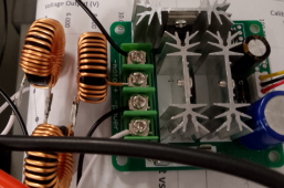
I think i'm just going to try the PWM controller and see how long it lasts, and maybe an inductor on the output before the inverter as well.

Failing that, i may also try plan B, with a DC SSR switched at about 500-1000Hz but they're about £50 so i don't want to do that just yet...


OK. Was worth a shot.
FYI 200W Micro Inverter:
Not something I can do:
 
So the addition of both an inline 0.1 Ohm resistor along with an added 10,000uF capacitor on the Microinverter input appears like it will reduce current ripple from a PWM or DCDC converter reaching the input capacitors of the Microinverter by close to 90%.

If you are planning to power your m250s through either PWM controllers or DC-DC converters, adding an 0.1 ohm resistor and 10,000uF capacitor to protect the Microinverter from current ripple seems like the safest way to do that and if you are willing to experiment, seeing how long an m250 without that protection lasts compared to one with it would be very interesting…
Thanks for this recap, it is very interesting to me.

I have just received some 100mH inductors and I am intending to try a LC filter on the pwm output, handily these have 0.1 ohm resistance as well which looks like it will be beneficial.

One thing I did notice is that the pwm duty to put 4a into the inverter was very low (just based on knob position) which hints at high instantaneous current to hit the average 4a. I think this will be a good clue to see if the filter improves things, and probably why the pwm unit was heating up quickly...
 
Well i've given it a try with some inductors.

1 made little difference, 2 was noticeably better then...

With 3 Dollatek 100uH inductors in series on the PWM output then feeding into the M250, the PWM board no longer gets hot, barely above room temperature running ~3A for a few minutes. I think this confirms that switching the current into the M250 is higher than you think unless there's something calming it down - the measured current on my PSU and the power output is an average but the peak is based on charging the capacitors and the impedance of the supply/wiring.
I did a quick and probably very inaccurate circuit sim and it did show that inductance in series is very helpful in reducing the switching currents down.

The PWM control knob still controls output power _reasonably_ well , but there's now another effect going on where i think the inverter is now trying to control the voltage/power input level and it's hunting a bit - by maybe 0.5A as measured on the PSU. I am now wondering if additional capacitance will help this or possibly a power resistor across the pwm unit...it just needs something to change the characteristics of the system a bit to stop it hunting.
 

Attachments

  • Inductors added.PNG
    Inductors added.PNG
    346.9 KB · Views: 4
Transistors switching inductor rather than capacitor lets the voltage drop be across inductor, so you've got something more like switching power supply.

When transistor turns off, current in inductor makes voltage fly to opposite polarity, which can blow up transistors. consider a snubber, clamping diode, etc.

It is very common for switching of inductive loads to kill transistors and burn relays.
 
Thanks for this recap, it is very interesting to me.

I have just received some 100mH inductors and I am intending to try a LC filter on the pwm output, handily these have 0.1 ohm resistance as well which looks like it will be beneficial.

One thing I did notice is that the pwm duty to put 4a into the inverter was very low (just based on knob position) which hints at high instantaneous current to hit the average 4a. I think this will be a good clue to see if the filter improves things, and probably why the pwm unit was heating up quickly...
Will be interested to learn what you discover…
 
Transistors switching inductor rather than capacitor lets the voltage drop be across inductor, so you've got something more like switching power supply.

When transistor turns off, current in inductor makes voltage fly to opposite polarity, which can blow up transistors. consider a snubber, clamping diode, etc.

It is very common for switching of inductive loads to kill transistors and burn relays.
I'm hoping the pwm unit will be ok with the inductors as it is designed to drive motors...
 
Oh, I was thinking PWM charger.
Yes, probably has reverse polarity protection diodes on its transistors.
But it never expected to drive a capacitive load. With PWM (part of a switcher), most of the power dissipation in transistor is during the voltage transitions, which takes a long time charging capacitor. Your inductor should do a lot to help that.
It certainly helps, without the inductors the switching transistor got very hot, it now doesn't.
 
I'm hoping the pwm unit will be ok with the inductors as it is designed to drive motors...
I can't recall whether dynamic control of battery-driven power is a priority to you or not, but as you add inductors it occurs to that you might want to get ahold of one of these: https://www.amazon.com/AITRIP-Conve...8TWKK5Z9/ref=psdc_10967761_t3_B0756HQTRM?th=1

I picked up 3 of these from AliExpress for less than half the price of each these 2 from Amazon, so once you start adding up the cost of inductors, PWM, etc... this quickly becomes a cost-effective fully-integrated solution.

8A max without added cooling = 200W max input power from a 25VDC battery translating to 160-180W max output assuming efficiency of 80-90%. By adding a fan, you should be able deliver 250W (or you can use 2 units in parallel).

You will need to boost by at least 2 volts so if your battery varies between 28.8V when fully-charged to 25V when fully discharged, you'll need to configure output voltage for 29.0V and then set the output current to 5.5-6.2A (depending on measured efficiency).

Current ripple and stability of output are the two criticisms that have been levelled against these cheapo DCDC boosters but since these are precisely the areas you are looking at and characterizing, could make sense to include one of these in the mix as a reference...
 
Oh, I was thinking PWM charger.
Yes, probably has reverse polarity protection diodes on its transistors.
But it never expected to drive a capacitive load. With PWM (part of a switcher), most of the power dissipation in transistor is during the voltage transitions, which takes a long time charging capacitor. Your inductor should do a lot to help that.
Here are some parameters I'll throw out at you in case you have a suggestion for size of inductor that could help:

PWM current: 40A
Duty Cycle: 10% @ 25kHz (4us ON, 36us OFF)
Input Capacitance being powered: 10,000uF
Maximum Ripple Current at Input: 8A
 
Back
Top