I recently picked up a bunch of used m250’s for ~$15 ea, am eager to test out some of the PWM ideas in this thread. They were cheap enough that I’m not too concerned about frying one or two or five in the process.
An
m250 teardown video from a few years back shows 4 input caps which appear to be
NCC KY-series . Those are billed as low ESR, long life, and high ripple tolerance - a happy surprise!
Welcome to the club.
I’m not sure which approach you are planning to use to get battery power into your m250s, but there a 3 different approaches being discussed here:
-direct connect - max current well in excess of any Iscmax spec is the risk but kundip has run for over two years now without issue. Current ripple and capacitor wear-out is not a concern with direct connect, merely the possibility of exceeding max current specs and whatever ill-effect that can have.
-through a DC-DC converter (most likely a booster) - current can be limited to stay under Iscmax spec, so that is no longer a concern but high-frequency current ripple may cause premature wearout of input capacitors. More on thought to prevent / limit that below. kundip has also run this configuration for over 2 years without issue.
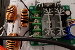
-through a PWM motor speed controller - this will also be current-limited to whatever the max rating of the PWM controller can be but 20A exceeds most Iscmax specs, so we are assuming it is average current of 10A or less that matter rather than peak current. PWM is the worst-case for current ripple and jimbob32 originally suggested this approach and is likely to be our first member to test it. I’ve also got some PWM controllers on the way to test this approach later this year.
You have not said how much power you are looking to generate, but if it is enough to allow you to use 2-4 of your Microinverters and you are willing to contribute to our evolving experiment, it would be fantastic if you could test 2-4 different approaches in parallel as kundip has done to learn which approaches are most problematic (which could take years to see before a failure materializes.
I’m interested in both the DCDC booster and PWM controller approach since I want a way to control / throttle output and so I’ve started modeling current ripple and simulating various approaches to reducing it.
This recap is addressed to both jimbob32 and you in case it gives you any ideas you want to test with either a PWM controller or a DC-DC-booster:
-50% DUTY-CYCLE: the closer to 50% duty cycle you can be using a PWM controller, the more you can minimize current ripple. So 20A @ 50% duty-cycle is a better way to generate 250W of power from a 25V battery than 40A @ 25% duty-cycle.
-INLINE RESISTANCE: adding an 0.1 Ohm or 0.05 Ohm power resistor in between the output of the PWM controller or DC-DC-converter greatly reduced the current ripple reaching the input capacitors of the Microinverter. My crude simulations show at least a 75% reduction in current ripple when adding an 0.1 ohm resistor inline between DC output and Microinverter input versus only 0.01 Ohms of wiring resistance. Note that addition of an 0.1 ohm resistor inline with 250W of power from a 24VDC battery will come at a cost of ~4% lost efficiency because of increased I^2R losses.
-ADDED INPUT CAPACITANCE: my Microinverters have 10,800uF of input capacitors on each DC input, so I’ve also simulated the effect of adding another 10,000 uF of input capacitance and the result is a further reduction of current ripple by close to 50%. I don’t believe doubling input capacitance is likely to interfere with a Microinverter’s ability to respond @ 60Hz as needed, but that is tough to model and could potentially result in some lost efficiency.
So the addition of both an inline 0.1 Ohm resistor along with an added 10,000uF capacitor on the Microinverter input appears like it will reduce current ripple from a PWM or DCDC converter reaching the input capacitors of the Microinverter by close to 90%.
If you are planning to power your m250s through either PWM controllers or DC-DC converters, adding an 0.1 ohm resistor and 10,000uF capacitor to protect the Microinverter from current ripple seems like the safest way to do that and if you are willing to experiment, seeing how long an m250 without that protection lasts compared to one with it would be very interesting…