diy solar

diy solar

POP Quiz! pumps & solar

tomy2

escape artist
Joined
Mar 12, 2022
Messages
433
Location
paso robles ca.
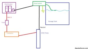
I'm wanting to switch a well house to solar and replaced the old 220V submersible pump with a 110V Grundfos 2wire pump. the installer just used one leg of the existing 220v to power the new pump and it works fine. But I want to replace the 220v feed with 110v. The easiest way to modify the wiring is to remove the L1 hot wire , and jump from L1 to L2 at points A & B [diagram]. When I do this the pump doesn't start! I have to switch it back to the 220v configuration to run it. I don't get it, everything is reading 110v, but the 110v pump does not like it. WHY? the Redneck diagram below is a clearer image of what i have , except i have a second hot wire from L2 to a fuse and to the contactor. the problem is that if I disconnect either L1 or L2, the pump won't start.
 
Last edited:
Trying to look at the drawing, I'm not understanding why you need a jumper between L1 and L2, you should be able to just use a single wire for 110v. Also, according to your drawing the pump is running 24/7 because the pump connects to the Neutral and Hots in the same box. If you're trying to use the float switch that joint needs to go away. The wiring is WAY over complicated here with too many Neutral connections all over the place. Also check your contactor for active points. Some cheaper split phase contactors have 1 leg always connected and only the 2nd leg is actually breaking. That's going to throw things all out of whack reusing it for single phase.

Well Wiring.jpg
 
Change out your 240vAC panel breaker to 2 separate 120vAC breakers (or 1 breaker and a blank). Use 1 for your well pump. If your previous wiring to your Well is 4 wire you would leave unconnected the conductor that is not the 1 hot lead to the 120vAC pump. The 3 wires left are hot, neutral and ground. I assume that the wire is sufficient size to carry the amperage. If not you will need to rewire.
 
Ok...
First, your original wiring shouldn't have been L1, L2, N

It should have been L1, L2,Ground...

So, you need to remove the 240V two pole breaker, install a single pole breaker rated for the pump breaker size make it L1, then take the old L2 circuit, and put it on the Neutral bus, leave the Ground where it was.
Leave the pump switch like it was.
Hook up new 120V pump...
Done.
Correctly, and safe.
 
you have to excuse my sloppy diagram. your diagram more accurately conveys the Neutral path. There is also a 110v booster pump inside the well house, which I was trying to ignore for simplicity sake, but it accomplished the opposite . The contactors are both open when not running. At first, I tried removing the fuses, one at a time, and the booster pump worked, but not the submersible. That is why i tried the jumper fix. I have already installed a new single phase breaker with 12guage wire going to a eGFI receptacle in the wellhouse, which will feed the pumps, once the other problem is resolved.
 
Ok...
First, your original wiring shouldn't have been L1, L2, N

It should have been L1, L2,Ground...

So, you need to remove the 240V two pole breaker, install a single pole breaker rated for the pump breaker size make it L1, then take the old L2 circuit, and put it on the Neutral bus, leave the Ground where it was.
Leave the pump switch like it was.
Hook up new 120V pump...
Done.
Correctly, and safe.
The original wiring was for a 220v pump and the option of using 220v for the booster pump. so the wiring is somewhat complicated .
 
The original wiring was for a 220v pump and the option of using 220v for the booster pump. so the wiring is somewhat complicated .
Still, the diagram shows L1,L2, N… and there should not be any Neutral in a 240V circuit. But there MUST me a ground.
 
But I want to replace the 220v feed with 110v.
At the risk of annoyingly questioning the premise, instead of answering your question... why? If you already have the wire there what is your motivation to change this?

Side note: All of the diagrams so far have neutrals flying around on their own. I doubt that's really true, I thought NEC didn't like that.
 
Still, the diagram shows L1,L2, N… and there should not be any Neutral in a 240V circuit. But there MUST me a ground.
there is a white wire from the breaker, that l call N. . the N and the ground wires are joined together in the fuse box, which should be ok since the main panel is 3 feet away. as a side question , I have a 220v minisplit powered from a subpanel. should that N wire go to the ground terminal ?
 
At the risk of annoyingly questioning the premise, instead of answering your question... why? If you already have the wire there what is your motivation to change this?

Side note: All of the diagrams so far have neutrals flying around on their own. I doubt that's really true, I thought NEC didn't like that.
the wire from the panel is over 30 years old and looks to be undersized .and if i replace it with a three wire, it will eliminate some of the confusion.
 
... I have already installed a new single phase breaker with 12guage wire going to a eGFI receptacle in the wellhouse, which will feed the pumps, once the other problem is resolved.
Depending on length of run that 12awg is good for 20a. If a 20a circuit can supply both pumps should be no problem.
 
the wire from the panel is over 30 years old and looks to be undersized .and if i replace it with a three wire, it will eliminate some of the confusion.
Do you already have the wire so you don't want to buy 4 wire? 120v panels always add confusion. It would be worth the cost if you're buying the wire I think to keep it full 240v.
 
Trying to look at the drawing, I'm not understanding why you need a jumper between L1 and L2, you should be able to just use a single wire for 110v. Also, according to your drawing the pump is running 24/7 because the pump connects to the Neutral and Hots in the same box. If you're trying to use the float switch that joint needs to go away. The wiring is WAY over complicated here with too many Neutral connections all over the place. Also check your contactor for active points. Some cheaper split phase contactors have 1 leg always connected and only the 2nd leg is actually breaking. That's going to throw things all out of whack reusing it for single phase.

View attachment 166359
i borrowed your diagram for an edit, hopefully the problem is clear now .
 
i borrowed your diagram for an edit, hopefully the problem is clear now .
You should not have a problem with one hot wire, one neutral wire (white is not always neutral in an older wiring setup sometimes it was L2 of a 240vAC) and a ground (bare copper). If your float is designed to work with 240vAC that might be a problem. If you are reusing some strange fuse arrangement that is not following polarity with wiring that might be a problem.

Start at one end and trace you circuit.
i wondered too about the float . it is a bunch of wires and some are hidden . i just got new fuses designed for 110v so we will see. thanks
 
Ok...
First, your original wiring shouldn't have been L1, L2, N

It should have been L1, L2,Ground...

So, you need to remove the 240V two pole breaker, install a single pole breaker rated for the pump breaker size make it L1, then take the old L2 circuit, and put it on the Neutral bus, leave the Ground where it was.
Leave the pump switch like it was.
Hook up new 120V pump...
Done.
Correctly, and safe.
it took me a couple days to WRap my head around putting a neutral wire where a hot one was. and i was hung up on the color of the wires. now, I understand that you easily solved the quiz. thanks, now I have a better understanding of 240v circuits.
 
Last edited:
it took me a couple days to WRap my head around putting a neutral wire where a hot one was. and i was hung up on the color of the wires. now, I understand that you easily solved the quiz. thanks, now I have a better understanding of 240v circuits.
Yup, ya just gotta remember... electricity doesn't care what color the wire is...
Inspectors do... put white tape on the wire.
Or, remove the black tape if present.
 
Yup, ya just gotta remember... electricity doesn't care what color the wire is...
Inspectors do... put white tape on the wire.
Or, remove the black tape if present.
Do you know what movie, the phrase [ Pop Quiz ] came from ? It involves a bomb squad.
 
Ok...
First, your original wiring shouldn't have been L1, L2, N

It should have been L1, L2,Ground...

So, you need to remove the 240V two pole breaker, install a single pole breaker rated for the pump breaker size make it L1, then take the old L2 circuit, and put it on the Neutral bus, leave the Ground where it was.
Leave the pump switch like it was.
Hook up new 120V pump...
Done.
Correctly, and safe.
even after the wiring was correctly changed to 120V, the pump would not start. Turns out that the float was controlled by a contactor with a 220V coil. once I replaced it with a 2 pole 120V contactor, it works fine. Now I want to power it with the off grid solar circuit, while keeping the float control intact. can i just reroute the black [hot] wire to the solar system, and keep the neutral wire as is? The solar system is stand alone.
 
even after the wiring was correctly changed to 120V, the pump would not start. Turns out that the float was controlled by a contactor with a 220V coil. once I replaced it with a 2 pole 120V contactor, it works fine. Now I want to power it with the off grid solar circuit, while keeping the float control intact. can i just reroute the black [hot] wire to the solar system, and keep the neutral wire as is? The solar system is stand alone.
Wild.
It's always something... good catch.
 
Back
Top